

OTUS - Obstacle Prevention
Sicuramente fra i primi obiettivi di un robot, dopo il movimento, cé la prevenzione ostacoli!
Se poi questo pesa oltre 10Kg e puó raggiungere e superare una velocitá di 1 m/s bé allora questo diventa anche un problema di sicurezza!
Per la sanitá del robot stesso aggiungerei anche quello di non rimanere incastrato o finire in una buca!
Sappiamo che la realtá, con tutte le sue casistiche, mette a dura prova i modelli che hanno la presunzione di scegliere in autonomia.
Giá perché finché é l'intelligenza dell'operatore a scegliere é assai facile ma quando é il robot stesso a scegliere in autonomia il problema diventa serio.
Comunque ho verificato che anche con i comandi manuali una funzione anti crash sempre attiva risulta utile.
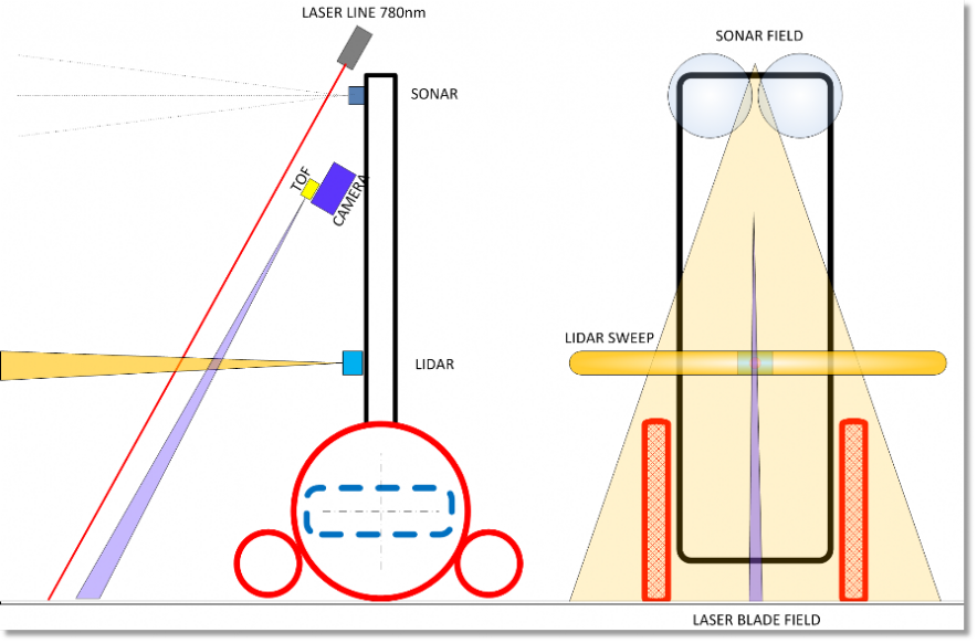
L'approccio seguito per la detezione degli ostacoli o della morfologia del terreno si basa su almeno tre tecnologie diverse:
- Sonar: Cé ne sono due posizionati sulle spalle del robot e coprono una vista frontale ed ortogonale al modello.
- TOF e LIDAR: Uno di questi é posizionato sulla camera mentre un secondo é posto centralmente ed in basso.
- Laser line: Questa tecnica implementata con una sorgente laser infrarosso produce una linea (che nello spazio diventa una lama) di fronte al robot. Questa linea viene ripresa dalla camera di bordo che facilmente la rivela ed é in grado di valutarne l'integritá. Da questo si valuta lo spazio disponibile a sinistra, destra, in salita o discesa oppure nulla! Per cui é bene fermarsi e pensare cosa fare! É stato scelto un laser infrarosso in quanto si ottengono riflessioni migliori da parte dei corpi, anche se esisteranno sempre dei casi limite. Uno di questi problemi é la navigazione all'aperto in pieno sole ma per questo vi invitiamo a leggere la documentazione del sistema di ripresa qui.
Qui sotto le geometrie in gioco viste lateralmente e frontalmente
Surely among the first objectives of a robot, after movement, there is obstacle prevention!
And if this weighs over 10Kg and can reach and exceed a speed of 1 m/s well then this also becomes a safety problem!
For the health of the robot itself I would also add that of not getting stuck or ending up in a hole!
We know that reality, with all its cases, puts a strain on models that have the presumption of choosing independently.
Yes, because as long as it is the operator's intelligence to choose it is very easy but when the robot itself chooses autonomously, the problem becomes serious.
However, I have verified that even with the manual controls an anti-crash function always active is useful.
The approach followed for the detection of obstacles or terrain morphology is based on at least three different technologies:
- Sonar: There are two positioned on the shoulders of the robot and cover a front view and orthogonal to the model.
- TOF and LIDAR: One of these is positioned on the chamber while a second is placed centrally and at the bottom.
- Laser line: This technique implemented with an infrared laser source produces a line (which becomes a blade in space) in front of the robot. This line is picked up by the on-board camera which easily reveals it and is able to evaluate its integrity. From this we evaluate the space available on the left, right, uphill or downhill or nothing! So it is good to stop and think what to do! An infrared laser was chosen as better reflections from the bodies are obtained, even if there will always be borderline cases. One of these problems is sailing outdoors in full sun but for this we invite you to read the documentation of the camera system here.
Below the geometries at stake seen from the side and front
I vari sensori menzionati hanno velocitá di risposta assai diverse, il piú lento é il sonar che puó richiedere 200ms mentre la piú veloce é la lettura della linea laser che richiede 16ms per catturare una immagine e 33ms per elaborarla, ma visto che la cattura dell'immagine avviene in "ombra" il tempo richiesto é di 33ms.
Questo é il tempo di elaborazione richiesto per rivelare un ostacolo, da cui ne deriverá la massima velocitá attuabile!
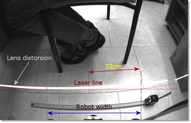
Infatti se posizioniamo il raggio laser troppo lontano dal modello avremmo difficoltá negli ambienti ristretti ma potremo avere velocitá di esercizio superiori, altresi una minore distanza nel posizionamento del laser ci impone una velocitá di esercizio piú bassa, questa é stata la nostra scelta ...
Qui trovate un pezzo di codice che analizza la linea laser e qui sotto potete vedere la linea ripresa da OTUS.
The various sensors mentioned have very different response speeds, the slowest is the sonar which can take 200ms while the fastest is the reading of the laser line which requires 16ms to capture an image and 33ms to process it, but since the capture of the image takes place in "shadow" the time required is 33ms.
This is the processing time required to reveal an obstacle, resulting in the maximum achievable speed!
In fact, if we position the laser beam too far from the model we would have difficulties in confined spaces but we could have higher operating speeds, also a shorter distance in the positioning of the laser requires us a lower operating speed, this was our choice ...
Here you will find a piece of code that analyzes the laser line and below you can see the line taken by OTUS.
Qui sotto riportiamo alcuni esempi di immagini riprese dal robot durante le sue esplorazioni ...
Below are some examples of images taken by the robot during its explorations ...
Infine qui sotto trovate due filmati dove si vede OTUS in azione in due diversi casi ....
Finally, below you will find two videos where we see OTUS in action in two different cases ....