

8.0 Thermal System Design Considerations
8.1 The first step in the design of a thermoelectric cooling system involves making an analysis of the system's overall thermal characteristics. This analysis, which may be quite simple for some applications or highly complex in other cases, must never be neglected if a satisfactory and efficient design is to be realized. Some of the more important factors to be considered are discussed in the following paragraphs. Although we have made certain simplifications that may horrify the pure thermodynamicist, the results obtained have been found to satisfy all but those few applications that approach state-of-the-art limits.
Please note that design information contained in this manual is presented for the purpose of assisting those engineers and scientists who wish either to estimate cooling requirements or to actually develop their own cooling systems. For the many individuals who prefer not to become involved in the details of the thermoelectric design process, however, we encourage you to contact us for assistance. Ferrotec America is committed to providing strong customer technical support and our engineering staff is available to assist in complex thermoelectric-related design activities.
8.2 ACTIVE HEAT LOAD: The active heat load is the actual heat generated by the component, "black box" or system to be cooled. For most applications, the active load will be equal to the electrical power input to the article being cooled (Watts = Volts x Amps) but in other situations the load may be more difficult to determine. Since the total electrical input power generally represents the worst case active heat load, we recommend that you use this value for design purposes.
8.3 PASSIVE HEAT LOAD: The passive heat load (sometimes called heat leak or parasitic heat load) is that heat energy which is lost or gained by the article being cooled due to conduction, convection, and/or radiation. Passive heat losses may occur through any heat-conductive path including air, insulation, and electrical wiring. In applications where there is no active heat generation, the passive heat leak will represent the entire heat load on the thermoelectric cooler.
Determination of the total heat leak within a cooling system is a relatively complicated issue but a reasonable estimate of these losses often can be made by means of some basic heat transfer calculations. If there is any uncertainty about heat losses in a given design, we highly recommend that you contact our engineering staff for assistance and suggestions.
8.4 HEAT TRANSFER EQUATIONS: Several fundamental heat transfer equations are presented to assist the engineer in evaluating some of the thermal aspects of a design or system.
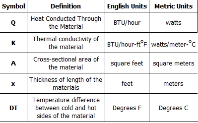
8.4.1 HEAT CONDUCTION THROUGH A SOLID MATERIAL: The relationship that describes the transfer of heat through a solid material was suggested by J.B. Fourier in the early 1800's. Thermal conduction is dependent upon the geometry and thermal conductivity of a given material plus the existing temperature gradient through the material. Although thermal conductivity varies with temperature, the actual variation is quite small and can be neglected for our purposes. Mathematically, heat transfer by conduction may be expressed as:
![]()
8.4.2 HEAT TRANSFER FROM AN EXPOSED SURFACE TO AMBIENT BY CONVECTION: Heat leak to or from an uninsulated metal surface can constitute a significant heat load in a thermal system. Isaac Newton proposed the relationship describing the transfer of heat when a cooled (or heated) surface is exposed directly to the ambient air. To account for the degree of thermal coupling between the surface and surrounding air, a numerical value (h), called the Heat Transfer Coefficient, must be incorporated into the equation. Heat lost or gained in this manner may be expressed mathematically as:
Q=(h)(A)(DT)

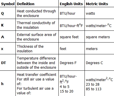
8.4.3 HEAT TRANSFER THROUGH THE WALLS OF AN INSULATED ENCLOSURE: Heat leak to or from an insulated container combines an element of thermal conduction through the insulating material with an element of convection loss at the external insulation surfaces. Heat lost from (or gained by) an insulated enclosure may be expressed mathematically as:

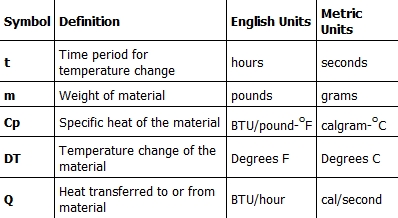
8.4.4 TIME NEEDED TO CHANGE THE TEMPERATURE OF AN OBJECT: Determination of the time required to thermoelectrically cool or heat a given object is a moderately complicated matter. For good accuracy, it would be necessary to make a detailed analysis of the entire thermal system including all component parts and interfaces. By using the simplified method presented here, however, it is possible to make a reasonable estimate of a system's thermal transient response.
![]()
Note (1): 1 Watt = 0.239 calories/second
Note (2): Thermoelectric modules pump heat at a rate that is proportional to the temperature difference (DT) across the module. In order to approximate actual module performance, the average heat removal rate should be used when determining the transient behavior of a thermal system. The average heat removal rate is:
![]()
Where: Qc at DTmin is the amount of heat a thermoelectric module is pumping at the initial object temperature when DC power is first applied to the module. The DT is zero at this time and the heat pumping rate is at the highest point.
Qc at DTmax is the amount of heat a thermoelectric module is pumping when the object has cooled to the desired temperature. The DT is higher at this time and the heat pumping rate is lower.
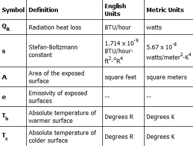
8.4.5 HEAT TRANSFER FROM A BODY BY RADIATION: Most thermoelectric cooling applications involve relatively moderate temperatures and small surface areas where radiation heat losses usually are negligible. Probably the only situation where thermal radiation may be of concern is that of a multistage cooler operating at a very low temperature and close to its lower limit. For such applications, it sometimes is possible to attach a small radiation shield to one of the lower module stages. By fabricating this shield so that it surrounds the upper stage and cooled object, thermal radiation losses may be reduced substantially.
As an indication of the magnitude of heat leak due to thermal radiation, consider the following. A perfect black-body having a surface area of 1.0 cm2 and operating at -100°C (173K) will receive approximately 43 milliwatts of heat from its 30°C (303K) surroundings. Be aware that the accurate determination of radiation loss is a highly complicated issue and a suitable heat transfer textbook should be consulted for detailed information. A very simplified estimation of such losses may be made, however, by using the equation given below.
![]()
8.4.6 R-VALUE OF INSULATION: The R-value of an insulating material is a measure of the insulation's overall effectiveness or resistance to heat flow. R-value is not a scientific term, per se, but the expression is used extensively within the building construction industry in the United States. The relationship between R-value, insulation thickness, and thermal conductivity may be expressed by the equation:
![]()
where:
x = Thickness of the insulation in inches
k = Thermal conductivity of the insulation in BTU/hr-ft-°F
Note: Insulation R-value normally is based on insulation thickness in inches. Since thermal conductivity values in Appendix B are expressed in feet, the k value in the equation's denominator has been multiplied by 12.
8.5 THERMAL INSULATION CONSIDERATIONS: In order to maximize thermal performance and minimize condensation, all cooled objects should be properly insulated. Insulation type and thickness often is governed by the application and it may not be possible to achieve the optimum insulation arrangement in all cases. Every effort should be made, however, to prevent ambient air from blowing directly on the cooled object and/or thermoelectric device.
Figures (8.1) and (8.2) illustrate the relationship between the heat leak from an insulated surface and the insulation thickness. It can be seen that even a small amount of insulation will provide a significant reduction in heat loss but, beyond a certain point, greater thicknesses give little benefit. The two heat leak graphs show heat loss in watts per square unit of surface area for a one degree temperature difference (DT) through the insulation. Total heat leak (Qtot) in watts for other surface areas (SA) or DT's may be calculated by the expression:
![]()
Figure (8.1)
Heat Leak from an Insulated Surface in Metric Units
Figure (8.2)
Heat Leak from an Insulated Surface in English Units