

Lasers: Safety, Diode Lasers, Helium Neon Lasers, Drive, Info, Parts
A Practical Guide for Experimenters and Hobbyists
Version 2.62
Copyright (C) 1994,1995,1996,1997
Samuel M. Goldwasser
Corrections or suggestions to: sam@stdavids.picker.com
--- All Rights Reserved ---
Reproduction of this document in whole or in part is permitted
if both of the following conditions are satisfied:
1. This notice is included in its entirety at the beginning.
2. There is no charge except to cover the costs of copying.
Both laser diodes and helium neon (HeNe) lasers are popular hobbyist projects.
This document includes information on both - hopefully it will grow in the future.
Our emphasis is on the care and feeding of these types of lasers. Thus, you will not find much information on the design of laser shows or holography experiments. I leave these to the many excellent books and articles that have been published over the years. However, on-line resources for driving laser diodes and powering helium neon lasers seem to be scarce. Some of those that exist are incorrect and potentially dangerous (or at least destructive).
This document was written in the hopes of rectifying this situation.
This document is still under development. Many of the circuits have been reverse engineered - traced from various schematics or actual hardware. There may be errors in transcription, interpretation, analysis, or voltage or current values listed. They are provided solely as the basis for your own designs and are not guaranteed to be 'plans' that will work for your needs without some tweaking. We are not responsible for damage to equipment, your ego, blown parts, county wide power outages, mini black holes, planetary disruptions, or personal injury that may result from the use of this material.
Laser Safety
You only received one set of eyeballs?
Lasers have tended to be high glamor devices popular with with hobbyists, experimenters, entertainers, and serious researchers alike. However, except for very low power lasers - those with less than a fraction of a mW of beam power - they do pose some unique hazards particularly with respect to instant and permanent damage to vision.
There are several reasons for this even for lasers which do not represent any sort of burning or fire risk:
* The output of many lasers is a parallel - collimated - beam which means that not only is the energy concentrated in a small area but the lens of the eye will focus it to a microscopic point on the retina instantly vaporizing tissue in much less than the blink of an eye. A collimated beam represents the rays from an object at infinity so if your eye is focused for distance, the laser will be in focus as well - to a microscopic point.
The output of a laser pointer or helium neon laser is a collimated beam.
Even at power levels considered relatively safe, one shouldn't deliberately stare into the beam for any reason. For these relatively low power lasers, permanent eye damage is not that likely but why take chances? For these lasers, viewing the spot projected on a white surface is perfectly safe.
* An output of 1 mW may not sound like much compared to a 100 W light bulb but consider:
A 100 W light bulb puts out about 2 or 3 W of visible light (the rest is mostly IR and heat) more or less uniformly distributed in all directions. However, at any reasonable distance from the light bulb, the power density (e.g., W/sq. mm) is much lower than for a collimated laser beam of even very low power. And, it takes significant effort to produce any sort of truly collimated beam from such a non-point source such as is present with even the filament of a clear light bulb.
For example, at 10 cm from a 100 W bulb (which would be a very uncomfortable place to be just due to the heat), the power density assuming 3 total watts of light would be only about .025 mW/sq. mm. At 1 m, it would be only .00025 mW/sq. mm or 250 mW/sq. m. Based on this back-of-the-envelope calculation, a 10 mW laser beam spread out to a circular area .2 m in diameter will be brighter than the 100 W light bulb at 1 m! And, close to the laser itself, that beam may be only 1 *mm* in diameter and 40,000 times more intense!
A popular graveyard joke in the laser industry is: "Do not stare into the beam with your remaining good eye". Nonetheless, laser safety is no laughing matter.
The most common types of lasers generally available to hobbyists - CD laser diodes, visible laser diodes, laser pointers, and small HeNe lasers, are all rated Class II or IIIa.
See the section: "Laser safety classification".
Class II lasers should be relatively low risk if even minimal precautions are taken.
However, Class IIIa lasers must be taken much more seriously if the beam is collimated - as it would be from a laser pointer or HeNe laser tube.
In addition, with helium neon lasers, high voltage power supplies are involved so there is the added shock hazard resulting from touching or accidentally coming in contact with uninsulated connections. See the document: "Safety Guidelines for High Voltage and/or Line Powered Equipment" before working on any type of equipment which uses line voltage or produces high voltage. Most of these are quite low power so the actual risk of electrocution from the high voltage side is relatively small but there may be AC line voltage involved and there can be collateral damage from a reflex response to the shock. In addition, a homemade power supply, in particular, may use components which are grossly oversized for the application (due to low cost availability) like a 15,000 V, 400 W neon sign transformer even though only under 10 W of power is actually needed (we definitely do NOT recommend this approach).
Furthermore, you may come across a truly high power CO2 or argon ion laser, or even a 50 mW helium neon tube. These, rated Class IIIb or Class IV, represent much more significant risks of both instant permanent eye damage even from momentary reflections from shiny (specular) surfaces as well a very real fire hazard. In addition there is a very real danger of electrocution from the high voltage high current power supplies used to power these beasts. Since this document does not deal with these types of lasers, the essential additional precautions that must be taken are not covered. However, you must handle them properly for your own safety and the safety of others around you and your surroundings.
The following very large number is designed to impress: The power density of a 1 mW laser beam when focused to a spot of around 2 um (which isn't difficult with a simple convex lens) is around 250,000,000 W per square meter!
Be Extremely Careful When Working with any laser!
LASER SAFETY CLASSIFICATION:
(From: Richard Trotman (trotman@udel.edu)).
I'm paraphrasing from "Introduction to Lasers", C.O.R.D., 1990:
Class I |
EXEMPT LASERS, considered 'safe' for intrabeam viewing. Visible beam. |
Class II |
LOW-POWERED VISIBLE (CW) OR HIGH PRF LASERS, won't damage your eye if viewed momentarily. Visible beam. |
Class IIIa |
MEDIUM POWER LASERS, focused beam can injure the eye. |
Class IIIb |
MEDIUM POWER LASERS, diffuse reflection is not hazardous, doesn't present a fire hazard. |
Class IV |
HIGH POWER LASERS, diffuse reflection is hazardous and/or a fire hazard. |
Diode Lasers
Introduction:
------------
Note: throughout this document, we will use the terms 'laser diode' and 'diode
laser' somewhat interchangeably.
Diode lasers use nearly microscopic chips of Gallium-Arsenide or other exotic
semiconductors to generate coherent light in a very small package.
Laser diodes are solid state devices not all that different from LEDs. The first laser diodes were developed quite early in the history of lasers but it wasn't until the early 1980s that they became widely available - and their price dropped accordingly. Now, there are a wide variety - some emitting *watts* of optical power. The most common types found in common devices like CD players and laser pointers have an output in the 3 to 5 mW range.
However, unlike LEDs, laser diodes require much greater care in their drive electronics or else they *will* die - instantly. See the sections on CD and visible laser diodes, below, before attempting to power or even handle them.
In their favor, laser diodes are very compact - the active element is about the size of a grain of sand, low power (and low voltage), efficient (especially compared to the gas lasers they replaced), rugged, and long lived if treated properly.
They do have some disadvantages in addition to the critical drive requirements. Optical performance is usually not equal to that of other laser types. In particular, the coherence length and monochromicity are likely to be inferior. This is not surprising considering that the laser cavity is a fraction of a mm in length formed by the junction of the III-V semiconductor between cleaved faces. Compare this to even the smallest common HeNe laser tubes with about a 10 cm cavity. Thus, most laser diodes would not be suitable light sources for holography or interferometry, for example.
However, for many applications, laser diodes are perfectly adequate and their advantages especially small size, low power, and low cost - far outweigh any faults. In fact, these 'faults' can prove to be advantageous where the laser diode is being used as a light source as unwanted speckle and interference effects are greatly reduced.
The most common types on the planet by far are those used in CD players and CDROM drives. These produce a (mostly) invisible beam in the near infrared part of the spectrum at a wavelength of 780 nm. The optical power output from the raw laser diodes may be up to 5 mW but once it passes through the optics, what hits the CD is typically in the .3 to 1 mW range.
Visible laser diodes have replaced helium neon lasers in supermarket checkout UPC scanners and other bar code scanners, laser pointers, patient positioning devices in medicine (i.e., CT and MRI scanners, radiation treatment planning), and many other applications. The first visible laser diodes emitted at a wavelength of around 670 nm in the deep red part of the spectrum. More recently, 650 nm and 635 nm red-orange laser diodes have dropped in price. Due to the nonuniformity of the human eye's response, light at 635 nm appears more than 4 times brighter than the same power at 670 nm. Thus, the newest laser pointers and other devices benefitting from visibility are using these newer technology devices. Currently, they are substantially more expensive than those emitting at 670 nm but that will change as DVDs become popular:
Laser diodes in the 635 to 650 nm range will be used in the much hyped DVD (Digital Video - or Versatile - Disc) technology, destined to replace CDs and CDROMs in the next few years. The shorter wavelength compared to 780 nm is one of several improvements that enable DVDs to store about 8 times (or more - 4 to 5 GB per layer) the amount of information or video/audio as CDs (650 MB). A side benefit is that dead DVD players and DVDROM drives (I cannot wait) will yield very nice visible laser diodes for the experimenter :-).
How do I use a Visible Laser Diode?
--------------------------------------------
The quick answer is *very carefully* for two reasons: I am assuming this is a typical 3 to 5 mW visible laser diode probably emitting at a wavelength in the 635 to 670 nm range.
1. You can easily destroy the typical laser diode through instantaneous overcurrent, static discharge, probing them with a VOM, or just looking at them the wrong way :-).
By far the easiest way to experiment with these devices is to obtain complete laser diode modules. Versions are available with both the drive circuitry and (adjustable) collimating optics. They are more expensive than raw laser diodes but are also virtually foolproof. Inexpensive laser pointers are one source for similar devices which may be adequate for your needs but modifying them is probably difficult. See the chapter: "Parts Sources" for suppliers of both raw laser diodes and laser diode modules.
2. Any time you are working with laser light you need to be careful with respect to exposure of a beam to your eyes. This is particularly true if you collimate the beam as this will result in the lens of your eye bringing it to a sharp focus with possible instantaneous retinal damage.
Typical currents are in the 30-100 mA range at 1.7-2.5 V. However, the power curve is extremely non-linear. There is a lasing threshold below which there will be no coherent output (though there may be LED type emission). For a diode rated at a typical current of 85 mA, the threshold current may be 75 mA. That 10 mA range is all you have to play with. Go to 86 mA (in this example) and your laser diode may be history in the blink of an eye.
This is one reason why most applications of laser diodes include optical sensing to regulate beam power. As the temperature of the laser diode changes (heats with use), the current requirements change as well.
The third lead is for an optical sensing photodiode used to regulate power output when used in a feedback circuit which controls your current. This is very important to achieve any sort of stable long term operation.
You can easily destroy a laser diode by exceeding the safe current even for an instant. It is critical to the life of the laser diode that under no circumstances do you exceed the safe current limit even for a microsecond!
Laser diodes are also extremely static sensitive, so take appropriate precautions when handling and soldering. Also, do not try to test them with an analog VOM which could on the low ohms scale supply too much current.
It is possible to drive laser diodes with a DC supply and resistor, but unless you know the precise value needed or have a laser power meter at your disposal, you can easily exceed the ratings before you realize it.
You might hear someone bragging "I have driven thousands of laser diodes by just connecting them to a battery and resistor and never have blown any". Sure, right. While it is quite possible that the susceptibility to instant damage due to overcurrent varies with the type of laser diode, unless you know the precise behavior, you must err on the side of caution. Some designers have gone to extremes, however.
For an actual application, you should use the optical feedback to regulate beam power. You should also use a heatsink if you do not already have the laser diode mounted on one.
The raw beam from a laser diode is generally wedge shaped - 10 x 30 degrees is a typical divergence. You will need a short focal length convex lens to produce anything approaching a collimated beam. The optics from a dead CD player (even though CD players and CDROM drives use infra-red laser diodes, the optics can likely still be used with visible laser diodes), a low to medium power microscope objective, or even an old disc camera can provide a lens that may be entirely suitable for your needs.
CD Player Laser Diodes
------------------------------
The major difference between these and the visible laser diodes discussed in the section: "How do I use a visible laser diode?" is that the output is near IR - usually at 780 nm (wavelengths from 400 to 700 nm are generally considered the visible portion of the electromagnetic spectrum). Therefore, you must use an IR detector device to even confirm laser emission.
Thus, they make truly lousy laser pointers or laser light shows as the emission is just barely visible in subdued light. If you hoped for a Star Wars type laser beam, better go hunting for a 25 W argon laser :-). However, for data or voice communications, various kinds of scanning or sensing, and electro-optic applications where visibility is not needed or not desirable, these low cost sources of coherent light are ideal.
Similar types are found in CDROM drives and CD-R recorders, Minidisc equipment, newer laserdisc players, magneto-optical drives. Other optical storage technology uses laser diodes as well. WORM drives, in particular, may use devices with higher power output - 30 mW or more. High resolution laser imagers, typesetters, and plotters may use laser diodes producing 150 mW or more. Take additional precautions if you have a laser diode from one of these (or don't really know where yours spent its earlier life). There are laser diodes with optical output measured in watts, though these will not be what you would call tiny and probably require buss bars for electrical power and plumbing for cooling!
CD laser diodes are infrared (IR) emitters, usually 780 nm, with a maximum power output of around 5 mW. There is also a very slightly visible deep red emission from all those I have seen. This may be a spurious very low power line in the red part of the spectrum or your eye's response to the near IR appearing red and about 10,000 times weaker than the actual beam. Despite what the EM spectrum charts show, the eye's response does not drop off to zero at exactly 700 nm so there decreasing sensitivity out to 800 nm or beyond depending on the individual. The main beam is IR and invisible. Take care. A collimated 5 mW beam is potentially hazardous to your eyes. Don't be misled into thinking the laser is weak due to the weak appearance of the beam. It is not supposed to be visible at all!
Typical CD laser optics put out about .3-1 mW at the objective lens though the diodes themselves may be capable of up to 4 or 5 mW depending on type. If you saved the optical components, these may be useful in generating a collimated or focused beam. The aspheric objective lens will be optimized for producing a diffraction limited spot about 1 to 3 mm from its front surface when the optical system is used intact.
The optics may include a collimating lens, diffraction grating (to produce the three beams in a three beam pickup), beam splitter prism or mirror, turning mirror (for horizontally mounted optics), and focusing (objective) lens. Older pickups tend to have larger and more substantial sets of optics. Despite their small size and low cost, these are very high quality optical components.
However, depending on design, some of the parts may be missing or combined into one component. For example, many Sony pickups do not appear to use a collimating lens. For pickups with a collimating lens, if the objective lens is removed, you should get a more or less parallel main beam and two weaker side beams. Mix and match optics for your needs (if you can get it apart non-destructively). Where there is no collimating lens, the objective lens may be used for this purpose if positioned closer to the laser diode.
WARNING: A collimated 5 mW beam is hazardous especially since it is mostly invisible. By the time you realize you have a problem it will be too late.
The coils around the pickup are used for servo control of focus and tracking by positioning the objective lens to within less than a um (1/25,400 of an inch) of optimal based on the return beam reflected from the CD. See the document: "Notes on the Troubleshooting and Repair of Compact Disc Players and CDROM Drives" for more information on optical pickup organization and operation.
Typical drive currents are in the 30 to 100 mA range at 1.7 to 2.5 V. However, the power curve is quite non-linear (though perhaps not as extreme as the typical visible laser diode). There is a lasing threshold below which there will be no coherent output (just IR LED emission). For a diode rated at a nominal current of 50 mA (typical for Sony pickups, for example), the threshold current may be 30 mA. This is one reason why most applications of laser diodes include optical sensing (there is a built in photodiode in the same case as the laser emitter) to regulate beam power. You can easily destroy a laser diode by exceeding the safe current even for an instant. It is critical to the life of the laser diode that under no circumstances do you exceed the safe current limit even for a microsecond!
Laser diodes are also supposed to be extremely static sensitive, so use appropriate precautions. Also, do not try to test them with an analog VOM which in particular could on the low ohms scale supply too much current. It is possible to drive laser diodes with a DC supply and resistor, but unless you know the precise value needed, you can easily exceed the ratings.
For an actual application, you should use the optical feedback to regulate beam power. You should also use a heatsink if you do not already have the laser diode mounted on one. CD laser diodes are designed for continuous operation.
Testing of Low Power Laser Diodes
---------------------------------------------
If you have pinouts and specifications for your laser diode, these procedures can be greatly simplified. The following assumes you know nothing about your device other than that it is a 3 to 5 mW laser diode.
The first step is to identify which pair of terminals are the laser diode and photodiode. Your laser diode assembly will be configured like one of the following: 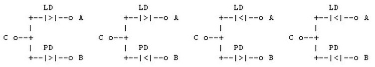
The photodiode's forward voltage drop will be in the approximately .7 V range compared to 1.7-2.5 V for the laser diode. So, for the test below if you get a forward voltage drop of under a volt, you are on the photodiode leads. If your voltage goes above 3 V, you have the polarity backwards. Warning: Some laser diodes have very low reverse voltage ratings and will be destroyed by modest reverse voltage. Check your spec sheet. However, the laser diodes found inn CD players seem to be happy with 4 or 5 volts applied in reverse. Of course, a shorted or open reading could indicate a defective laser diode or photodiode. The metal case is often one of the terminals, probably C but not always.
If the laser diode is still connected to its circuitry (probably a printed flex cable), it is likely that the laser diode will have a small capacitor directly across its terminals and the optical sensing photodiode will be connected to a resistor or potentiometer. In particular, this is true of Sony pickups and may help to identify the correct hookup.
Either of the circuits below can be used to identify the proper connections and polarity and then to drive the laser diode for testing purposes.
* One approach that works for testing is to use a 0 to 10 VDC supply with a current limiting resistor in series with the diode: 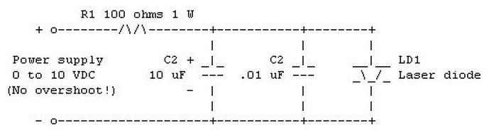
If your power supply has a current limiter, set it at 50 or 60 mA to start.
You can always increase it later.
* Alternatively, a fixed supply with a potentiometer can be used: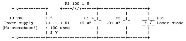
R2 limits the maximum current. If you know the specs for your diode, this
is a good idea (and to protect your power supply as well). You can always
reduce its value if your laser diode requires more than about 85 mA (with
R2 = 100 ohms).
The two capacitors provide some filtering to reduce the risk of a transient
blowing the laser diode. C2 should be mounted close to the laser diode.
Before attempting to obtain lasing action with either of these circuits,
monitor the voltage across what you think is the laser diode as you slowly
increase the power supply or potentiometer.
* If you guessed correctly (or have the pinout diagram from the spec sheet
or determined from its former life), the voltage will increase until around
1.5 to 2 V and then climb more slowly. Don't push your luck unless you are
also monitoring the laser diode current and optical output.
* If you are across the laser diode or photodiode in the reverse biased
direction, the voltage will continue to climb above 2 V without slowing.
Don't push your luck here - the breakdown voltage of the laser diode may
be only a little more than this and - you guessed it - exceeding this is
not healthy for the laser diode either.
* If you are on the photodiode in the forward direction, the voltage will get
stuck around .7 V.
Once you have identified the correct connections, monitor the current through
the laser diode as you check for a laser beam.
* For IR laser diodes, you *must* use an IR detector circuit, card, video
camera or camcorder (with the requisite 3 hands) to monitor for an actual
IR laser beam.
Note: If you are trying to use a video camera or camcorder as an IR detector,
confirm its sensitivity to near IR by looking at an active IR remote control
through its viewfinder. It may have a built in IR blocking filter which will
prevent it from being sensitive to IR. This may be removable.
* For visible laser diodes, you can use your eyeballs or any more sophisticated
detector as desired. Look from an oblique angle or better yet, place a white
card a couple of inches in front of the laser diode. Even a 1 mW laser diode
is an intense source of light - there will be no doubt when lasing begins.
Some typical operating currents for laser diodes of various wavelengths are
listed below. THESE ARE JUST EXAMPLES. Your laser diode may have a lower
operating current than the ones listed here! The lasing threshold may be as
little as 5 or 10 mA below the operating current and the operating current may
be 5 mA or less below the maximum current.
Wavelength Operating Current
808 nm 60 - 70 mA
780 nm 45 - 55 mA
670 nm 30 - 35 mA
660 nm 55 - 65 mA
650 nm 65 - 85 mA
640 nm 70 - 90 mA
Of course, if you inherited a bag of identical laser diodes and can afford to
blow one: (1) I could use a few before you do this :-) and (2) you probably
could fairly accurately characterize them by testing one to destruction.
For a current below the lasing threshold for your laser diode, there will be
some emission due to simple LED action. As you slowly increase the current,
at some point (if the laser diode is good) as you exceed the threshold current,
the character of the emission will change dramatically and a very slight
increase in laser diode current will result in a significant increase in
intensity. Congratulations! The laser diode is lasing.
CAUTION: unless you have a laser power meter, don't push your luck. The
maximum safe current may be as little as 5% above the lasing threshold. Go
over by 6% and your diode may be history. The exponential power curve seems
to be steeper with visible laser diodes but there is no way to be sure without
specifications. It is all too easy to convert laser diodes into extremely
useless DELDs - Dark Emitting Laser Diodes - or very expensive LEDs.
I have used this approach with laser diodes from dead CD players without
difficulty. In the case of many of these, the operating current is printed
on a sticker on the optical block, often as a 3 digit number representing
the current in 10ths of mAs. Typical values are 35 to 60 mA (350 to 600).
Sony pickups typically average around 50 mA. Without this information, the
best you can do is to estimate when it is lasing at the proper intensity by
comparing the brightness of the 'red dot' one sees by looking into the lens
from a safe distance at an oblique angle. However, this is not very reliable
as the optical power at the objective lens depends on the particular CD player.
Reasons to leave the CD laser diode in the optical block:
-------------------------------------------------------------------------
There are several good reasons to leave your CD laser diode installed in the
optical block assembly even if you are not going to use it with the objective
lens and focus and tracking actuators:
1. The pickup block provides the very important heat sink which is necessary for continuous operation.
2. There is less risk of damaging it through careless handling and ESD.
3. There may be a collimator lens in there - probably the first or second optical element in front of the laser diode. It may be combined with the laser diode in its metal barrel. If there is a collimator, you should be able to get a nice nearly parallel beam without much work. At most, a small lens will be needed to optimize it.
Remove the objective (front) lens and its associated coils unless you require them for a short range application. They will likely come off as a unit without too much effort. However, try not to destroy this assembly as you never can tell what might be needed in the future.
4. The multisegment photodiode sensor and focus and tracking actuators may be useful for a variety of applications.
While there are many variations on the construction of optical pickups even from the same manufacturer, they all need to perform the same functions so the internal components are usually quite similar.
Here is the connection diagram for a typical Sony pickup: 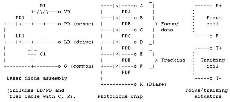
The laser diode assembly and photodiode chip connections are typically all on a single flex cable with 10 to 12 conductors. The actuator connections may also be included or on a separate 4 conductor flex cable. The signals may be identified on the circuit board to which they attach with designations similar to those shown above. The signals A,C and B,D are usually shorted together near the connector as they are always used in pairs. The laser current test point, if present, will be near the connections for the laser diode assembly.
It is usually possible to identify most of these connections with a strong light and magnifying glass - an patience - by tracing back from the components on the optical block. The locations of the laser diode assembly and photodiode array chip are usually easily identified. Some regulation and/or protection components may also be present.
Note: There are often a pair of solder pads on two adjacent traces. These can be shorted with a glob of solder (use a grounded soldering iron!) which will protect the laser diode from ESD or other damage during handling and testing. This added precaution probably isn't needed but will not hurt. If these pads are shorted, then there is little risk of damaging the laser diode and a multimeter (but do not use a VOM on the X1 ohms range if it has one) can be safely used to identify component connections and polarity.
Laser diode life:
---------------------
For all intents and purposes, laser diodes in properly designed circuits do not degrade significantly during use or when powered on or off. However, it doesn't take much to blow them (see the sections: "How do I use a visible laser diode?" and "CD player laser diodes"). I have seen CD players go more than 10,000 hours with no noticeable change in performance. This doesn't necessarily mean that the laser diode itself isn't gradually degrading in some way - just that the automatic power control is still able to compensate fully. However, this is a lower bound on possible laser diode life span.
Some datasheets list expected lifetimes for laser diodes exceeding 100,000 hours - over 12 years of continuous operation. Of course, I trust these about as much as the latest disk drive MTBFs of 1 million hours :-).
Laser diodes that fail prematurely were either defective to begin with or, their driver circuitry was inadequate, or they experience some 'event' resultling in momentary (greater than a few microseconds) overcurrent.
As noted elsewhere, a weak laser diode is well down on the list of likely causes for CD player problem
Of course, in the grand scheme of things, even LEDs gradually lose brightness with use.
How sensitive are laser diodes, really?:
---------------------------------------------------
Not all laser diodes are created equal and their susceptibility to damage through improper handling or improper drive likely varies widely. Here is a discussion of some of the issues:
From: Eric Rechner (erechner@jetstream.net)).
"Does anyone have any experience with Hitachi laser diode HL7843MG 5 mW 780nm? I find this diode to be possibly extremely sensitive (ESD??), more so than any other 780nm laser diode. Does anyone know if there are problems with Hitachi MQW type diodes? Are MQW diodes more sensitive to ESD than Double Heterojunction diodes? Does anyone have info on possibly 'bad' or defective lasers out there?"
(From: Jon Elson (jmelson@artsci.wustl.edu)).
Strange. I think I've used some of these. I hear everybody babbling about extreme static sensitivity on these devices, yet I've never had a failure, and I've been using just the usual minimum precautions with any semiconductor device. I suspect that people may be exceeding the optical power MAXIMUMS on the devices. I've been very conservative on that, since the devices only carry an optical maximum, and don't have that correlated to forward diode current (difficult, because it varies strongly with temperature). I try to run them at a good bit less than rated power, maybe 2-3 mW optical output. I'm using a diode sold by Digi-Key for $19.00, just because it is cheaper than the Panasonic in the 5.4 mm case. I think the manufacturer is NVG or something like that. I've got 10 of them I am working with, designing a closed-loop driver for a photoplotter, which pulses the lasers on and off as fast as 10 uS on, 10 uS off. It is working pretty well now. I included a series resistor (as well as the control transistor), so that if the loop becomes unstable or the sensing diode gets disconnected, it won't fry the laser diode.
(From: Dr. Mark W. Lund (lundm@xray.byu.edu)).
The babbling starts here: You don't have to be a total idiot to blow these things, in fact I have blown a few myself. Identifying the source of the trouble is extremely costly and difficult because it only takes a spike of a few nS to to the damage. I would say that 99.9999% of the time it is the power supply. Either it spikes on turn-on, turn-off, or at random. We used to toast lasers with a $5,000 laser diode power supply that would spike every time you sent certain signals on the IEEE 488 control line. This was a tough one to figure out, I can tell you. In the process we tried to damage one using static to try to get a handle on the sensitivity, but were not able to get a catastrophic failure this way (we may have induced some latent failures, however). Other laser diodes may vary.
(From: Jon Elson (jmelson@artsci.wustl.edu)).
Ah! This is good anecdotal evidence! I've often suspected that there might be more of this going on, and instead of examining the drivers, people just attribute problems to an invisible gremlin! I sure can see how a closed circuit driver can oscillate or overshoot on transients, and there could be a situation where some percentage of drivers will be less stable due to component tolerances. Unless you rigorously test a good batch of your drivers, you could have this sort of thing and not know it. (Of course, any time you put a computer in the loop, especially one that is canned inside an instrument, then the probability of unanticipated gremlins increases dramatically!).
Of course, I was designing a fixed-purpose driver to be used in a specific application, inside an instrument, so I had it easier than the guys designing a lab-quality pulser for who knows what application. So, I could put in a resistor, which will limit current to some 'safe' level, even if the loop is unstable, which it certainly was when I was tuning up my driver.
I DO use generally sound anti-static precautions, almost subconsciously, to protect all semiconductor devices. But, I am aware that I have occasionally, by accident, touched a cable going to the laser diode before I was grounded, and I have never noted a catastrophic failure. I will have to go through some rigorous life-testing to make sure I'm not causing latent failures, but I've run these diodes for quite a few hours while testing things, and nothing of note has turned up yet.
By babbling, I meant some items in print media, as well as a lot on this and other newsgroups, indicating that if you even touch one lead of a diode laser, it is ABSOLUTELY destroyed, with a probability of 1.000! Obviously not true! Your comments are well reasoned, and indicate real experience. Others have also written that only a huge corporation, with millions in test equipment, could ever make their own laser diode driver. Now, clearly, the nanosecond multi-watt pulsers ARE much more difficult to do right, fast risetimes without overshoot is tricky. But, I did it in my basement with just over $1,000 in test equipment, mostly a decent oscilloscope. I also had the confidence that if I DID blow a few diodes, it wasn't so painful at $19 each.
So, now, I'm babbling!
IR detector circuit:
-------------------
This IR Detector may be used for testing of IR remote controls, CD player laser diodes, and other low level near IR emitters.
Component values are not critical. Purchase photodiode sensitive to near IR (750-900 um) or salvage from opto-coupler or photosensor. Dead computer mice, not the furry kind, usually contain IR sensitive photodiodes. For convenience, use a 9V battery for power. Even a weak one will work fine. Construct so that LED does not illuminate the photodiode!
The detected signal may be monitored across the transistor with an oscilloscope. 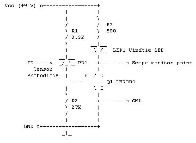
Divergence of Laser Diode:
-----------------------------------
(Portions from: Mark W. Lund (lundm@physc1.byu.edu)).
The divergence specification for laser diodes is measured to the half power points. T full width at the 10% level may be more like 70 or 80 degrees than the 30 degrees in the specifications.
A simple short focal length lens will collimate the beam. However, laser diodes tend to be astigmatic which means that you will have one axis collimated at a different focus than the other. A typical value for this astigmatism is 40 microns. A cylindrical lens in addition to the spherical collimating lens or a special lens designed for this purpose can correct this but may not be needed for non-critical applications.
Any camera lens will be able to produce a reasonably well collimated beam (subject to the astigmatism mentioned above). Put the laser diode it at the focal point of the lens. If you want the type of narrow beam produced by a HeNe laser, you need a short focal length lens, such as a microscope objective. A good compromise between cheap and short focal length would be an old disk camera lens. These cameras can be found at thrift shops, garage or yard sales, and flea markets for a couple dollars or less.
The longer the focal length the larger your beam will be, but the less effect the astigmatism will have. The diameter of the beam will be the size of the aperture of the lens (in which case you are throwing away light) or the size of the beam at the distance of one focal length, whichever is less.
Why can't an LED be focused like a laser diode?:
------------------------------------------------------------------
The cheap laser diode from a CD player can be focused to a spot less than 2 um in diameter. Why is this not possible with an LED?
The quick answer is that an LED does not appear as a point source and has as effective emitting area which is huge compared to a laser diode. Even though the emitting area of a laser diode is not a point, due to the way the laser beam is generated - collimation wise - it appears as a point source.
And, a point source can be focused to another point.
The effective emitting area of an LED is perhaps .25 x .25 mm. To focus an incoherent source like this to a 2 um spot with imaging optics would require a ratio of distances of roughly 125:1 for the LED-to-lens compared to the lens-to-image plane.
With any kind of real world optics, you will get a vanishingly small amount of power at the image plane.
Similarly, an LED beam cannot be cleaned up with a spatial filter (pinhole) as very little of the beam will make it through.
The laser diode is coherent and monochromatic (enough) that relatively simple optics can be used to focus it to a spot smaller than 2 um. While the dimensions of the laser diode chip are not all that much different from the LED, the characteristics of the laser emission makes such focusing a relatively easy task.
Consider that the beam from a HeNe or ruby laser doesn't come from point source either. The beam can be sharply focussed because it is very well collimated.
The availability of relatively cheap laser diodes really was the enabling technology for the CD revolution.
(From: Steve Nosko (q10706@email.mot.com)).
If a beam of light has nothing but *precisely* parallel rays, it can be focused to a point. Also, if the beam originated from a point, a lens will focus it to a point.
An LED has neither of these. First, it is an area source and light coming from that surface is not parallel. It would also be called a diffuse source, meaning light from all places on the surface travels in many directions. This kind of source can not be focused to anything but a smaller image of itself. The shorter the focal length of the lens, the smaller the image - but it is still an image of the source, not a spot. It is because of these rays, traveling in different directions, that a lens can't focus them all to the same point. If you draw the side view of a lens and trace rays this all should be obvious.
The gas laser, on the other hand, has rays which are much much closer to being parallel. The diode laser has rays which appear to come from an apparent point inside the diode.
There are two more subtle effects. One effect is the relatively wide range of wavelengths in the LED versus the narrow range of a laser. Simple optics don't focus all wavelengths at the same focal length. So the wide bandwidth of the LED causes a little trouble. There is another effect having to do with the size of the lens (diffraction limit) and the wavelength, but this is also secondary to an understanding of the *primary* reason why an LED can't be focused. I'll only talk about the largest effect due to the extended, non collimated source.
One thing to note is that the laser diode actually has two apparent point sources. One for the wide axis of the beam and another for the narrow axis. This means that the lens must be more like two crossed cylindrical lenses with different focal lengths. There are different types of laser diodes with varying degrees of this so that some are easier to to design lenses for. There probably are types, by now, where there aren't two.
I think of it like this (right or wrong). The astigmatism has two components. One is the difference in divergence between the two axes. I think this can be even if there is ONLY one apparent point source. It is just a point source with an oval aperture letting light through. The other is the different apparent point sources for the two axes.
Comments on driving laser diodes without optical feedback:
---------------------------------------------------------
(From: Dwight Elvey (elvey@civic.hal.com)).
If you intend to use the laser without the feedback, one has to realize that there are a number of problems. One is that as the temperature goes down, the laser efficiency goes up. This tends to cause the laser diode to destroy itself at lower temperatures while running that same current that was OK at some higher temperature. Generally, if the temperature doesn't vary to much, one can use something as simple as a limiting resistor and not run the laser at its highest output. I once made a burn-in driver for some power lasers that used constant current sources that had no feed back but I had to preheat the diodes to 100 degrees C before using that high a level of current. The level of current used would have wiped the diodes out at room temperatures.
The hardest part of the whole thing was making the circuit to have controlled levels of current during power on and power off. Most things like op-amps are not specified under these conditions. My first attempt wiped out 10 diodes :-( when I turned the power on.
To run the diodes at there maximum light out safely, requires using the feed back photo diode.
Visibility of Near-IR (NIR) laser diodes:
----------------------------------------
The following describes an interesting and convincing experiment. I would tend to believe these results concluding that the visible light from a CD laser diode is probably a spurious emission rather than the human eye's weak sensitivity to 780 nm radiation. The fact that the red emission was undiminished even after the laser diodes were damaged by overcurrent is further confirmation of these conclusions. If the red is a spurious (LED-like) emission, it should appear below the laser threshold suggesting another test.
(From: Kjell Kraakenes (kkraaken@telepost.no)).
I once used 780 nm laser diodes similar to the types used in CD players, and something that puzzled me was that I was able to see some red radiation from these diodes. I used a microscope objective to focus the light on a wall a few meters away, and when properly focused, a red spot was visible to the naked eye. I had a piece of black card board on the wall, and there was no specular reflection. I used an IR viewer of the type sold by Edmund Scientific (Find-R-Scope), and if I looked at the spot with this IR viewer the beam appeared defocused. By adjusting the distance between the laser diode and the microscope objective, the spot (as it appeared through the IR viewer) could be brought to a better focus. The red, visible light was then so much defocused that it was no longer visible to the naked eye. From these observations, I assumed that the spot I saw through the IR viewer was the laser emission at 780 nm, and that the visible light was some weak emission at a shorter wavelength. Because of the chromatic aberrations in the microscope objective these two wavelength could not be expected to be in focus simultaneously. I did not notice whether the distance between the laser diode and the microscope objective was increased or decreased when shifting between the focus of the visible and the IR light, but since I did not know the chromatic aberrations of the microscope objective this information would not help me.
I damaged a few of these laser diodes. Probably by burning one of the facets such that the lasing threshold was increased. Electrically they were OK, and the visible output appeared as intense as before, but the total output was only a few microwatts.
I therefore believe that the light people see from NIR laser diodes is spurious emission within the visible band, and not intense NIR radiation.
(From: Don Klipstein (Don@Misty.com)).
Some nominally IR wavelengths are indeed very slightly visible. In favorable conditions (mainly isolating from more visible wavelengths) I have seen with my own eyes:
1. The 766.49/769.9 nM potassium lines, as a contaminant in high pressure sodium lamps.
2. The 818.3/819.5 nM sodium lines in the spectra of high pressure sodium lamps.
3. The 762.1, 759.4, and 822.85 nM earth atmospheric absorption lines in the solar spectrum. (Usually with the sun somewhat low.)
4. The output of a laser diode in my CD player is visible at eye-safe intensities (half a meter from a source with a beam covering nearly a steradian for a few seconds). I have seen the spectrum of this along with that of a neon lamp placed next to it, and verified that what I saw was the laser line, with a wavelength around 800 nM. It could be as low as around 780 nM.
According to the C.I.E. "Y" or visibility function (or extrapolation thereof), the visibility of these lines is impressively low. However, considering the wide dynamic range of the human eye, these wavelengths are visible at eye-safe levels.
CAUTION: there is no advance warning of having exceeded eye-safe exposure to slightly visible wavelengths normally considered IR. You may permanently toast part of your retinas duplicating the above unless you verify retinal exposure below the Class I laser exposure limit.
I recently got a laser pointer with a wavelength of 660-661 nm or so and (guesstimated) 2 mW of output power.
I discovered that if I shine the beam through one of those dielectric interference bandpass filters, I got some weak beam output at other wavelengths. So, I investigated further.
About (very roughly estimated from standard issue eyeballs) .2 percent of the beam is spurious radiation with a continuous spectrum. I don't yet know well what it does at longer wavelengths, but a majority of the short wavelength side of this is in the few tens of nm below 660 nm. Slight traces exist down to 540 nm. With two 532 nm filters, I could stare into the beam and see a dim point of light. With a 570 nm filter, it was slightly bright to stare into and I could see the beam VERY DIMLY on a wall in a dark room. With a filter around 630 nm, I could easily see the beam on a wall in a dark room. I used my diffraction grating to verify that most of this was continuous spectrum in the passband of the filter.
The spurious radiation takes the same path that the laser radiation does.
With no filter, I could not see any continuous spectrum with my diffraction grating. The laser line was so much stronger.
As for IR lasers? If the spectrum is just a long-shifted version of what my visible laser does, the most visible part of the laser output would be the laser line. Having a wavelength 100 nm closer to visible increases its visibility only by about a factor of 1,000 and the total spurious output was (roughly) 1/1,000 of the laser line output. The wavelength of the bulk of this was nowhere near 100 nm shorter.
Although I can't be sure this would always be the case, the only spectrum components I could see using a diffraction grating with my CD player laser was the laser line at about 800 nm.
I suspect different IR laser diodes may have greatly different ratios of laser and LED output. If the LED output is only a fraction of a percent of the laser output, the visible output would be mainly the slightly visible laser line. If the LED output is equal to a few percent or more of the laser output, then it may be more visible than the laser line.
When will we see green and blue diode lasers?:
---------------------------------------------
(Portions from: Adam Cohen (adc20@eng.cam.ac.uk)).
Blue and green has been widely demonstrated by SHG (second harmonic generation a.k.a. frequency doubling) in nonlinear crystals (lithium niobate, KTP et al.), organic nonlinear materials, etc. etc.
The direct emission from a semiconductor has been the Holy Grail for several years. The semiconductor materials available with a sufficiently wide band-gap are notoriously difficult to deposit and cleave....But several groups are close to a commercial device now. In Japan, Nichia Chemicals, Sony, Pioneer and Toshiba (see p26 of Laser Focus World, March 1997) are all working on GaN-based devices (active layer in the Toshiba device is actually InGaN). I think 3M and some other US firms were concentrating on ZnSe, which emits at a slightly longer wavelength (more blue-green than blue)....
Helium-Neon Lasers
Introduction
A helium neon (henceforth abbreviated HeNe) laser is basically a fancy neon sign with mirrors at both ends. Well, not quite, but really not much more than this. The gas fill is a mixture of helium and neon gas at low pressure. A pair of mirrors (one totally reflective, the other partially reflective at the wavelength of the laser's output) complete the resonant cavity. This is called a Fabry-Perot cavity (if you want to impress your friends). The mirrors may be internal (common on small and inexpensive tubes) or external. Electrodes sealed into the tube allow for the passage of high voltage DC current to excite the discharge.
I remember doing the glasswork for a 3 foot long HeNe laser which included joining side tubes for the electrodes and exhaust port, fusing the electrodes themselves to the glass, preparing the main bore (capillary), and cutting the angled Brewster windows (so that external mirrors could be used) on a diamond saw. I do not know if the person building the laser ever got it to work but suspect that he gave up or went on to other projects (which probably were also never finished).
Some die-hards still construct their own HeNe lasers from scratch. Once all the glasswork is complete, the tube must be evacuated, baked to drive off surface impurities, backfilled with a specific mixture of helium to neon at a pressure of between 2 and 5 Torr (normal atmospheric pressure is about 760 Torr - 760 mm of mercury), and sealed. The mirrors must then be painstakingly positioned and aligned. Finally, the great moment arrives and the power is applied. You also constructed your high voltage power supply from scratch, right? With luck, the laser produces a beam and only final adjustments to the mirrors are then required. All sorts of things can go wrong. With external mirrors, the losses may be too great resulting in insufficient optical gain in the resonant cavity. The gas mixture may be incorrect or become contaminated. Seals might leak. It just may not be your day! Nonetheless, if you really want to be able to say you built a laser from the ground up, this is the approach to take.
However, for most of us, 'building' a HeNe laser is like 'building' a PC: An inexpensive HeNe tube and power supply are obtained, mounted, and wired together. Optics are added as needed. Power supplies may be home-built as an interesting project but few have the desire, facilities, patience, and determination to construct the actual HeNe tube itself.
The most common sealed HeNe laser tubes are between 6" and 14" (150 mm to 350 mm) in overall length and 1" to 1-1/2" (25 mm to 37.5 mm) generating optical power from .5 mW to 5 mW.
Slightly smaller tubes (less than .5 mW), somewhat larger tubes (up to 20 mW), and much larger tubes with internal or external mirrors (a *meter* or more in length generating up to 250 mW of optical power), are also available and may turn up on the surplus market. Specialized configurations - a triple XYZ axis triangular cavity laser in a solid glass block for an optical ring laser gyro, for example - also exist but are much much less common - you probably won't find one of these at a local flea market!
Manufacturers include Aerotech, Melles-Griot, Siemens, Spectra-Physics, and many others.
HeNe lasers used to be found in all kinds of equipment including early laser printers, laserdisc players, small laser shows, optical surveying and tunnel boring systems, medical positioning systems, and supermarket checkout UPC and other barcode scanners. (You can tell if you local ACME supermarket uses a HeNe laser in its checkout scanners by the color of the light - the 632.8 nm wavelength beam from a HeNe laser is noticeably more orange than the 670 nm deep red from a typical laser diode type.)
Nowadays, these applications are likely to use the much more compact lower (drive) power solid state laser diodes. Thus, a 5 mW laser pointer complete with batteries can conveniently fit on a keychain and generate the same beam power as a HeNe laser half a meter long!
So why bother with a HeNe laser at all? There are several reasons:
* For many applications including holography and interferometry, the high quality stable beam of a HeNe laser is unmatched (at least at reasonable cost, perhaps at all) by laser diodes. In particular, the coherence length and monochromicity of even a cheap HeNe laser are excellent and the beam profile is circular (laser diodes usually have some amount of astigmatism) so that simple spherical optics can be used for beam manipulation.
* As noted in the chapter on laser diodes, it is all too easy to ruin them in the blink of an eye (actually, the time it takes light to travel a few feet). It would not take very long to get frustrated burning out $50 diodes. So, the HeNe laser tube may be a better way to get started. They are harder to damage through carelessness or design errors. Just don't get the polarity reversed or exceed the tube's rated current for too long - or drop them on the floor! And, take care around the high voltage.
* Laser diode modules at a wavelength of 635 nm may be somewhat more expensive than surplus HeNe tubes with power supplies. However, with the introduction of DVD players and DVDROM drives, this situation probably will not last long.
HeNe Laser Safety:
As with *any* laser, proper precautions must be taken to avoid any possibility of damage to vision. The types of HeNe lasers dealt with in this document are classified as type II, IIIa, or the low end of IIIb (see the section: "Laser safety classification". For most of these, common sense (don't stare into the beam) and fairly basic precautions suffice since the reflected or scattered light will not cause instantaneous injury and is not a fire hazard.
However, unlike those for laser diodes, HeNe power supplies utilize high voltage (several KV) and some designs may be potentially lethal. This is particularly true of AC line powered units since the power transformer may be capable of much more current than is actually required by the HeNe laser tube - especially if it is home built using the transformer from some other piece of equipment (like an old tube type console TV or that utility pole transformer you found along the curb) which may have a much higher current rating.
The high quality capacitors in a typical power supply will hold enough charge to wake you up - for quite a while even after the supply has been switched off and unplugged. Unless significantly oversized, this isn't usually a lethal amount of energy but can still be quite a jolt. The HeNe tube itself also acts as a small HV capacitor so even touching it should it become disconnected from the power supply may give you a tingle. This probably won't hurt you physically but your ego may be bruised if you then drop the tube and it shatters on the floor! Use an insulated 1 M, 2 W resistor to drain the charge before touching anything.
Comments on HeNe Laser Safety issues:
(Portions from: Robert Savas (jondrew@mail.ao.net)).
A 10 mw HeNe laser certainly presents an eye hazard.
According to American National Standard, ANSI Z136.1-1993, table 4 Simplified Method for Selecting Laser Eye Protection for Intrabeam Viewing, protective eyewear with an attenuation factor of 10 (Optical Density 1) is required for a HeNe with a 10 milliwatt output. This assumes an exposure duration of 0.25 to 10 seconds, the time in which they eye would blink or change viewing direction due the the uncomfortable illumination level of the laser. Eyeware with an attenuation factor of 10 is roughly comparable to a good pair of sunglasses (this is NOT intended as a rigorous safety analysis, and I take no responsibility for anyone foolish enough to stare at a laser beam under any circumstances). This calculation also assumes the entire 10 milliwatts are contained in a beam small enough to enter a 7 millimeter aperture (the pupil of the eye). Beyond a few meters the beam has spread out enough so that only a small fraction of the total optical power could possible enter the eye.
Instant HeNe Laser theory:
The term laser stands for "Light Amplification by Stimulated Emission of Radiation". However, lasers as most of us know them, are actually sources of light - oscillators rather than amplifiers. (Although laser amplifiers do exist in applications as diverse as fiber optic communications repeaters and multi-gigawatt laser arrays for inertial fusion research.) Of course, all oscillators - electronic, mechanical, or optical - are constructed by adding the proper kind of positive feedback to an amplifier.
All materials exhibit what is known as a bright line spectra when excited in some way. In the case of gases, this can be an electric current or (RF) radio frequency field. In the case of solids like ruby, a bright pulse of light from a xenon flash lamp can be used. The spectral lines are the result of spontaneous transitions of electrons in the material's atoms from higher to lower energy levels. A similar set of dark lines result in broad band light that is passed through the material due to the absorption of energy at specific wavelengths. Only a discrete set of energy levels and thus a discrete set of transitions are permitted based on quantum mechanical principles (well beyond the scope of this document, thankfully!). The entire science of spectroscopy is based on fact that every material has a unique spectral signature.
The HeNe laser depends on energy level transitions in the neon gas. In the case of neon, there are dozens if not hundreds of possible wavelength lines of light in this spectrum. Some of the stronger ones are near the 632.8 nm line of the common red-orange HeNe laser - but this is not the strongest:
The strongest red line is 640.2 nm. There is one almost as strong at 633.4 nm. That's right, 633.4 nm and not 632.8 nm. The 632.8 nm one is quite weak in an ordinary neon spectrum, due to the high energy levels in the neon atom used to produce this line.
There are also many infra-red lines and some in the orange, yellow, and green regions of the spectrum as well.
The helium does not participate in the laser (light emitting) process but is used to couple energy from the discharge to the neon through collisions with the neon atoms. This pumps up the neon to a higher energy state resulting in a population inversion meaning that more atoms in the higher energy state than the ground or equilibrium state.
It turns out that the upper level of the transition that produces the 632.8 nm line has an energy level that almost exactly matches the energy level of helium's lowest excited state. The vibrational coupling between these two states is highly efficient.
You need the gas mixture to be mostly helium, so that helium atoms can be excited. The excited helium atoms collide with neon atoms, exciting some of them to the state that radiates 632.8 nm. Without helium, the neon atoms would be excited mostly to lower excited states responsible for non-laser lines.
A neon laser with no helium can be constructed but it is much more difficult without this means of energy coupling. Therefore, a HeNe laser that has lost enough of its helium (e.g., due to diffusion through the seals or glass) will most likely not lase at all since the pumping efficiency will be too low.
There are many possible transitions from the excited state to a lower energy state that can result in laser action. The most important (from our perspective) are listed below:
Wavelength Color
543.5 nm Green
593.9 nm Yellow
611.8 nm Orange
632.8 nm Red-Orange
1152.3 nm Near Infra-Red
3391.3 nm Mid Infra-Red
While we normally don't think of a HeNe laser as producing an infra-red (and invisible) beam, the IR spectral lines are quite strong. In fact, the first HeNe laser operated at 1152.3 nm. HeNe lasers at all of these wavelengths are commercially available but those operating at 632.8 nm are by far the most common and least expensive.
When the HeNe gas mixture is excited, all possible transitions occur at a steady rate due to spontaneous emission. However, most of the photons are emitted with a random direction and phase, and only light at one of these wavelengths is usually desired in the laser beam. At this point, we have basically the glow of a neon sign with some helium mixed in!
To turn spontaneous emission into the stimulated emission of a laser, a way of selectively amplifying one of these wavelengths is needed and providing feedback so that a sustained oscillation can be maintained. This may be accomplished by locating the discharge between a pair of mirrors forming what is known as a Fabry-Perot resonator or cavity. One mirror is totally reflective and the other is partially reflective to allow the beam to escape.
These mirrors are normally made to have peak reflectivity at the desired laser wavelength. When a spontaneously emitted photon resulting from the transition corresponding to this peak happens to be emitted in a direction nearly parallel to the long axis of the tube, it stimulates additional transitions in excited atoms. These atoms then emit photons at the same wavelength and with the same direction and phase. The photons bounce back and forth in the resonant cavity stimulating additional photon emission. Each pass through the discharge results in amplification - gain - of the light. If the gain due to stimulated emission exceeds the losses due to imperfect mirrors and other factors, the intensity builds up and a coherent beam of laser light emerges via the partially reflecting mirror at one end. With the proper discharge power, the excitation and emission exactly balance and a maximum strength continuous stable output beam is produced.
Spontaneously emitted photons that are not parallel to the axis of the tube will miss the mirrors entirely or will result in stimulated photons that are reflected only a couple of times before they are lost out the sides of the tube. Those that occur at the wrong wavelength will be reflected poorly if at all by the mirrors and any light at these wavelengths will die out as well.
Modes of Operation:
The physical dimensions of the Fabry-Perot resonator impose some additional constraints on the resulting beam characteristics. While it is commonly believed that the 632.8 (for example) transition is a sharp peak, it is actually a gaussian - bell shaped - curve. In order for the cavity to resonate strongly, a standing wave pattern must exist. This will only occur when an integral number of half wavelengths fit between the two mirrors. This restricts possible axial or longitudinal modes of oscillation to: 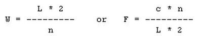
where:
* L is the distance between the mirrors (m)
* W denotes the possible wavelengths of oscillation (m)
* n is a large integer (order of 948,000 for W around 632.8 nm, L = .3 m)
* F denotes the possible frequencies of oscillation (Hz)
* c is the speed of light (approximately 300 million m/s).
The laser will not operate with just any wavelength - it must satisfy this equation. Therefore, the output will not usually be a single peak at 632.8 nm but a series of peaks around 632.8 nm spaced c/(L * 2) Hz apart. Longer cavities result in closer mode spacing and a larger number of modes since the gain won't fall off as rapidly as the modes move away from the peak. For example, a cavity length of 150 mm results in a longitudinal modes spacing of about 1 GHz; L = 300 mm results in about 500 MHz. The strongest spectral lines in the output will be nearest the combined peak of the lasing medium and mirror reflectivity but many others will still be present. This is called multimode operation.
Think of the vibrating string of a violin or piano. Being fixed at both ends, it can only sustain oscillations where an integer number of cycles fits on the string. In the case of a string, n can equal 1 (fundamental) and 2, 3, 4, 5 (harmonics or overtones). Due to the tension and stiffness of the string, only small integer values for n are present with a significant amplitude. For a HeNe laser, the distribution of the selected neon spectral line and shape of the reflectivity function of the mirrors with respect to wavelength determine which values of n are present. For a typical HeNe laser tube, possible values of n will form a series of very large numbers like 948,123, 948,124, 948,125, 948,126,.... rather than 1, 2, 3, 4 :-).
For example: 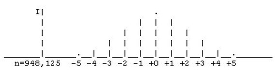
This also means that as the tube warms up and expands, these spectral line frequencies are going to drift downward (toward longer wavelengths). However, since the reflectivity distribution of the mirrors remains constant, new lines will fill in from above so the overall shape of the output doesn't change. 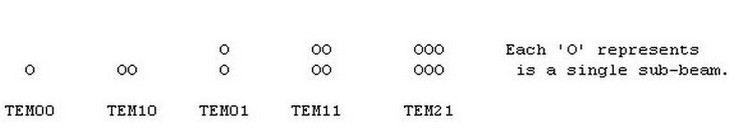
Other (non-cartesian) patterns of modes may also be possible depending on tube dimensions and operating conditions.
Early vs. modern HeNe lasers
In the first HeNe lasers (see the diagram below), exciting the gas atoms to the higher energy level was accomplished by coupling a radio frequency (RF) source (i.e., a radio transmitter) to the tube via external electrodes. Modern HeNe lasers almost always operate on a DC discharge via internal electrodes. 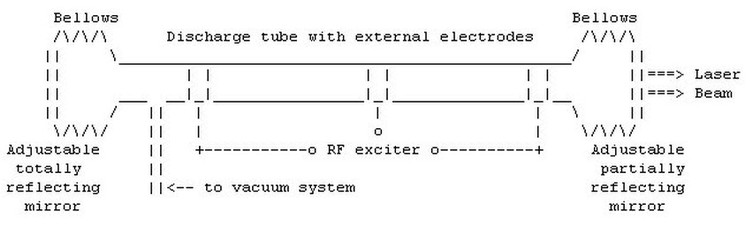
Early HeNe lasers were also quite large and unwieldy in comparison to modern devices. A laser such as the one depicted above was over 1 meter in length but could only produce about 1 mW of optical beam power! The associated RF exciter was as large as a microwave oven. With adjustable mirrors and a tendency to lose helium via diffusion under the electrodes, they were a finicky piece of laboratory apparatus with a lifetime measured in hundreds of operating hours.
In comparison, a modern 1 mW sealed HeNe laser tube can be less than 150 mm (6 inches) in total length, may be powered by a solid state inverter the size of a stick of butter, and will last more than 20,000 hours without maintenance of any type or a noticeable change in its performance characteristics.
This fabulous ASCII rendition of a typical small HeNe laser tube should make everything perfectly clear :-). 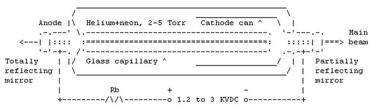
(Note: the main beam may emerge from either end of the tube depending design, not necessarily the cathode end as shown.)
* The anode (+) end is simply a small cylindrical metal electrode with a mirror fused or glued to its end.
The discharge at this end produces little heat or damage due to sputtering.
* The cathode (-) end is also a cylindrical metal electrode with a mirror fused or glued to its end but in addition, there is a large 'cylindrical can attached to the cathode and extending about half the length of the tube.
The discharge at this end is distributed over the entire area of the can thereby spreading the heat and minimizing damage due to sputtering which results from positive ion bombardment.
* These mirrors are not silvered or aluminized (metal coated) but are a type called 'dichroic'. They are made by depositing many alternating layers of hard but transparent materials having different indexes of refraction. The thickness of each is precisely 1/2 the wavelength of the laser light (632.8 nm being the most common for a HeNe laser). This results in reflection by interference with very high (>99.9 %) efficiency - much greater than for even the best metal coated mirrors.
* One of the mirrors will be nearly totally reflecting and the other will only be partially reflecting at the laser wavelength. Since the reflection peaks at a single wavelength, these mirrors actually appear quite transparent to other wavelengths of light. For example, for common HeNe lasers tubes, the mirrors transmit blue light quite readily and appear blue when looking through an unpowered (!!) tube.
* The mirrors will likely not have any 'user' adjustments. However, the cylindrical end pieces are mounted by thinner sections of metal tubing so that some slight changes to alignment may be possible with appropriate fixtures. Don't be tempted: (1) grabbing the high voltage electrodes is not likely to be pleasant and (2) it is too easy to break the seal if you get carried away. There should be no reason for the alignment to have changed unless you whacked the tube - it was set at the factory.
* The main beam will emerge from the partially reflecting mirror but this may be at either end of the tube depending on model. For example, where the tube is enclosed in a metal barrel, the HV connections will be to the anode end and the beam will exit from the cathode end. With this arrangement, the positive output of the power supply and ballast resistor can be very close to the tube anode and the entire barrel can be connected to the negative output of the power supply and earth ground.
* Since the mirrors are not perfect, there will be a weaker beam visible from the other end if that mirror is not covered (blocked or painted over). One use of this is to permit monitoring of laser power for purposes of optical power regulation or other closed loop applications.
* The major discharge is forced to take place inside a thick glass capillary tube with an inner bore of roughly 1 mm. This concentrates the discharge forcing operation in the most common and desirable TEM00 mode.
* The cheap surplus HeNe tubes do not generally produce a fixed polarized beam. The polarization will either be random or slowly changing as the tube heats. Tubes with a specified polarization are also available but are generally more costly. Lasers with external mirrors and Brewster windows will be linearly polarized and really pricey (and more finicky).
* These tubes are nearly always operate in multimode (longitundial) with a TEM00 beam profile. See the section: "Instant HeNe laser theory" for more info.
* Power for a HeNe laser is provided by a special high voltage power supply (see the section: "Basic HeNe power supply considerations" and consists of two parts (these maximum values depend on tube size (typical 1 to 10 mW tube is assumed):
- Operating voltage of 1,000 to 3,000 DC at 3 to 10 mA.
Like any discharge tube, the HeNe laser is a negative resistance device. As the current *increases* through the tube, the voltage across the tube *decreases*. The incremental magnitude of the negative resistance also increases with descreasing current.
- Starting voltage of 5 to 12 KV at almost no current. In the case of a HeNe tube, the initial breakdown voltage is much greater than the sustaining voltage. The starting voltage may be provided by a separate circuit or be part of the main supply.
* With a constant voltage power supply, a series ballast resistor is essential to limit tube current to the proper value. A ballast resistor will still be required with a constant current or current limited supply to stabilize operation. The ballast resistor may be included as part of a laser head but will be external for a bare tube.
In order for the discharge to be stable, the total of the effective power supply resistance, ballast resistance, and tube (negative) resistance must be greater than 0 at the operating point. If this is not the case, the result will be a relaxation oscillator - a flashing or cycling laser!
* Every HeNe tube will have a nominal current rating. In addition to excessive heating and damage to the electrodes, current beyond this value does not increase laser beam intensity. In fact, optical output actually decreases (probably because too high a percentage of the helium/neon atoms/ions are in the excited state). You can easily and safely demonstrate this behavior if your power supply has a current adjustment or you run an unregulated supply using a Variac. While the brightness of the discharge inside the tube will increase with increasing current, the actual intensity of the laser beam will max out and then eventually decrease with increasing current. (This is also an easy way of determining optimal tube current if you have not data on the tube - adjust the ballast resistor or power supply for maximum optical output and set it so that the current is at the lower end of the range over which the beam intensity is approximately constant.)
* These may be 'bare' tubes or encased in a cylindrical or rectangular laser head - or something in between.
- Bare tubes require clip-on connections to the power supply or high voltage connector and an external ballast resistor.
Advantages: Less expensive, discharge is fully visible resulting in an interesting display.
Disadvantages: Fragile, exposed high voltage terminals, need to provide your own mounting, wiring, and ballast resistor.
- Laser heads will usually come with an internal ballast resistor (though you may still need additional resistance to match the tube to your power supply). The high voltage cable will likely use an 'Alden' connector. The Alden connector is designed to hold off the high voltages with a pair of keyed recessed heavily insulated pins. This is a universal standard for small-medium HeNe laser power supplies (the longer fatter pin is negative).
Advantages: High voltage safely insulated, wiring is already done for you, relatively robust, easily mounted.
Disadvantages: More expensive, discharge not readily visible, repairs to wiring (unlikely to be needed) difficult.
* The operating lifetime of a typical HeNe laser tube is greater than 15,000 hours when used within its specified ratings. Therefore, this is not a major consideration for most hobbyist applications. However, the shelf life of the tube depends on its construction. There are two types of (sealed) HeNe tubes:
- Most better HeNe tubes (possibly all tubes manufactured in the last 10 years) are 'hard sealed' - the mirrors are fused to their respective electrodes by a low temperature glass 'frit' - sort of like solder for glass! These do not leak - at least not on any time scale that matters. Shelf life is essentially infinite.
- Older tubes have their mirrors just glued - Epoxied to the end electrodes. This adhesive leaks and such tubes have a shelf life of a few years - they fail by just sitting around doing nothing. This means that a bargain tube may not be such a bargain if it is beyond its expiration date (yes, just like dates on milk containers) as it may have a very limited life, be hard to start, weak or erratic, or may not work at all. You probably won't see any of these - at least not in a working condition.
* The efficiency of the typical HeNe laser is pretty pathetic. For example, a 2 mW HeNe tube powered by 1,400 V at 6 mA has an efficiency of less than .025 %. More than 99.975 percent of the power is wasted in the form of heat and incoherent light (from the discharge)! This doesn't even include the losses of the power supply and ballast resistor.
* The most common HeNe lasers by far produce light at a wavelength of 632.8 nm in the red-orange part of the visible spectrum - well into the region of the human eye's high sensitivity (but not as good as green). Thus, a 1 mW HeNe laser will appear brighter than a 4 mW laser diode operating at 670 nm.
* Green, yellow, and orange HeNe lasers are also available but are not nearly as 'efficient' as the common red-orange type. Thus, they are also much more costly for the same power since the spectral lines that need to be amplified are weaker at these wavelengths and therefore, the tubes must be larger.
Typical maximum output available from 'small' sealed tubes for various colors: green - 2.0 mW, yellow - 7.0 mW, orange - 7.0 mW, and red - 15 mW.
IR (infra-red) HeNe laser tubes are also available. However, an invisible beam just doesn't seem as exciting!
* The width of the beam as it emerges from the tube is typically between .5 mm and 1 mm - the inside bore diameter of the capillary discharge tube.
* The beam from a HeNe laser is already very well collimated even without external optics (unlike a laser diode which has a raw divergence measured in 10s of degrees). The divergence measured in milliradians (1 mR is less than 1/17th of a degree) is usually one of the tube specifications. A small HeNe tube may have a divergence of 1 to 2 mR. Divergence is affected mostly by beam (exit or waist) diameter (wider is better). Other factors like the ratio of length to bore diameter (narrower is better) may also affect this slightly. The equation for a plane wave source is:
So, for an ideal HeNe laser with a 1 mm bore at 632.8 nm, the divergence angle will be about .806 mR. Note that although a wider bore should result in less divergence, this also permits more not quite parallel rays to participate in the lasing process. Also see the section: "Improving the collimation of a laser".
Typical HeNe tube characteristics
(Portions from: Steve Nosko (q10706@email.mot.com)).
The following are typical of small (bare) red-orange (632.8 nm) HeNe tubes: 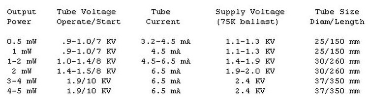
Melles Griot, Uniphase, Siemens, PMS, and Aerotech all show similar values.
Note that for a given optical power level, there can be substantial variation in the tube size. Typically, longer tubes will require higher start and operating voltages. And no, you cannot get a 3 mW tube to output 30 mW - even instantaneously - by driving it 10 times as hard!
HeNe tubes of other colors exist but are probably rare on the surplus market. They are not that common to begin with and are more expensive when new since for a given power level, the tubes must be larger and thus have higher voltage and current ratings due to their lower efficiency (the spectral lines being amplified are much weaker than the one at 632.8 nm).
There are infrared HeNe tubes as well. Yes, you can have a HeNe and it will light up inside (typical neon orange glow), but if there is no output beam (at least you cannot see one), you could have been sold an infrared HeNe tube. The IR may be visible with a video camera (assuming it doesn't have an IR blocking filter) or bu using one of the IR detector circuits or an IR detector card as discussed with respect to IR laser diodes.
As a side note... It is strange to see the orange glow in a green HeNe laser tube but have a green beam emerging. A diffraction grating or prism really shows all the lines that are in the glow discharge. Red through orange, yellow and green, even several blue lines!! The IR lines are present as well - you just cannot see them.
How can I tell if my tube is good?
A variety of problems can prevent a HeNe tube from lasing properly or make it hard to start.
* Physical damage. Obviously if the tube arrived in pieces, this is a shipping, not a technical problem :-).
* Misaligned mirrors. Using the tube as a hammer might bend the mirror mount at one end or the other. There are ways of determining and adjusting this alignment but they require some optical components and special jigs. Without these, adjustments are hit or miss (mostly miss) and will more likely result in a broken seal than anything else :-(. Problems with mirror alignemnt are very unlikely to occur with these tubes unless you were working hard at it!
* Loss of gas fill. This may result in a total inability to start or sustain the discharge. There is usually a metal sealing nipple at one end. This might be damaged.
* Incorrect gas fill. There may be a glow but the laser output will likely be weak or non-existent. The normal color of the discharge is whitish red-orange - a somewhat unsaturated version of the red-orange glow of a (true) neon sign.
- Loss of helium (from diffusion through the glass or seals) will result in the glow becoming deeper red-orange and less white. There will be little or no emission at the wavelength of helium's spectral lines. It probably isn't worth the effort to refill but see the section: "Recharging HeNe tubes".
- A leak which has allowed some air to enter (but where it is not totally up to atmostpheric pressure) will result in a glow with a white or pink color. Depending on the actual pressure, the intensity will vary as well.
If you can sustain a discharge but it is the wrong color (weak or white/pink color), you may have one of those really old Epoxy sealed tubes that leak and air has leaked in. Again, probably not worth repairing.
* Damaged electrodes or mirrors due to running with the power supply polarity reversed or greatly excessive current for a prolonged period of time. I don't know exactly what the physical effects might be but I would suspect metal sputtering from the negative electrode coating the mirror at that end of the tube. Buy another tube.
Improving the collimation of a HeNe laser
The following applies to any laser which outputs a substantially parallel beam but is written specifically for HeNe lasers. Collimation of laser diodes require a slightly different approach.
Although the divergence of a HeNe laser is already pretty good without any additional optics, the rather narrow beam as it exits from the tube (typically 1 mm) results in a beam with a typical divergence between 1 to 2.5 mR (order of 1 mm per meter or worse) if no other optics are used.
As noted in the section: "HeNe laser operation", beam divergence is inversely proportional to the beam diameter. Thus, it can be reduced even further by passing the beam through a pair of positive lenses - one to focus the beam to a point and the second to collimate the expanded beam.
A small telescope can be used to collimate a laser beam and will be easier to deal with than individual lenses. (This is how laser beams are bounced off the moon but the telescopes aren't so small.) Using a telescope is by far the easiest approach in terms of mounting - you only need to worry about position and alignment of two components - the laser tube and telescope.
If you want to use discrete optics:
* The focusing lens should have a short focal length (F1) such as a microscope or telescope eyepiece (e.g., F1 of 10 mm) or low power microscope objective (e.g., 10X). Note: the objective lens from a dead CD player has an ideal focal length - about 4 mm - but is aspheric and would probably not be that great but give it a try!
This will focus the laser beam to a (diffraction limited) point F1 in front of the lens from which it will then diverge.
* The collimating lens should be a large diameter medium focal length (e.g., 15 mm D2, 100 mm F2) lens placed F2 from the focus of the first lens.
For optimal results, the ratio of collimating lens diameter to focal length (D2/F2) should greater than or equal the ratio of HeNe beam diameter to focusing lens focal length (D1/F1). This will ensure that all the light is captured by the collimating lens.
The beam will be wider initially but will retain its diameter over much longer distances. For the example, above, the exit beam diameter will be about 10 mm resulting in nearly a 10 fold reduction in divergence.
Adjust the lens spacing to obtain best collimation. A resulting divergence of less than 1 mm per 10 meters or more should be possible with decent quality lenses - not old Coke bottle bottoms or plastic eyeglasses that have been used for skate boards :-).
HeNe laser tube life
Neon signs last a long times - years - how about HeNe laser tubes?
Lifespans of HeNe laser are long - 20,000 or more operating hours are typical. Shelf life of non-hard sealed tubes is limited by diffusion of the Helium atoms. Helium atoms are slippery little devils. They diffuse through almost anything. In the case of HeNe tubes, diffusion takes place mostly through the Epoxy adhesive used to mount the mirrors in non-hard sealed tubes (not common anymore) and through the glass itself but at a much much slower rate.
The gas doesn't 'wear out'. However, excessive or reverse current can degrade performance after a while. Electrode material may sputter onto the adjacent mirrors or excessive heat dissipation may damage the electrodes themselves.
A HeNe tube, when properly connected has much of its heat dissipated by the bombardment of positive ions at the cathode (the big can electrode) which is made large to spread the effect and keep the temperature down. Hook a tube up backwards and you may damage it in short order!
Recharging HeNe tubes
"I have two large tube green HeNes and and a 1 micron IR HeNe that are dead from obvious low helium pressure (spectrum from grating shows only weak He lines) has anyone had any success with putting tubes in a pressure chamber filled with Helium so it diffuses the other way?"
HeNe tubes which do not laser well or at all due to loss of helium can sometimes be rejuvenated by soaking them in helium at normal atmospheric pressure for a few days or weeks.
The point to realize is that it is the partial pressure of each gas that matters. Neon is a relatively large atom and does not diffuse through the tube at any rate that matters. However, helium is able to diffuse even when the pressure difference is small.
Even for a HeNe tube at 2 Torr, the partial pressure of helium is much greater than its partial pressure in the normal atmosphere. So, helium leaks out even though the total pressure outside is several hundred times greater. Conversely, soaking a HeNe tube in helium at 1 atmosphere will allow helium to diffuse into the tube at several hundred times the rate at which it had been leaking out. Thus, only a few days of this treatment may be needed if the problem is low helium pressure.
This hardly seems worthwhile for a $25 1 mW HeNe tube but it is something to keep in mind for other more substantial types.
(From: Mark W. Lund (lundm@xray.byu.edu)).
I have rejuvenated HeNes with low Helium pressure. Since the partial pressure of 1 atmosphere helium is much higher than inside the tube you don't really need to use high pressure, or even increased temperature. I just put them in a garbage bag and blasted some helium into it from time to time. The length of time necessary in my case was a few days, but depending on the glass type, thickness, and sealing method this may vary. It would be good to test the power every couple of days so you don't overshoot too much.
One warning, helium has a lower dielectric strength than air, so don't try to operate the laser in helium, it may arc over.
Items of Interest - General laser information
What makes a laser power meter so expensive?
Commercial laser power meters cost $300 and up - $1,000 is a more typical price for something that works over a wide range of power levels and wavelengths. Where the precision and automatic wavelength calibration of these instruments is not needed, a basic laser power meter can be built inexpensively. See the section: "Sam's super cheap and dirty laser power meter".
There are several ways to design a device that will determine the power in a beam of light. Here are two:
* Photodiode - each photon within the wavelength range of the device creates an electron-hole pair. When reverse biased, this results in a current flow which is proportional to light flux.
* Thermo-electric - the beam hits a sensor that absorbs (nearly) 100 pecent of the incident light energy at the range of wavelengths in question - a black body. This raises its temperature with respect to a known reference with a known thermal resistance between them.
Here are some comments on these approachs:
(From: Bill Sloman (sloman@sci.kun.nl)).
The important thing to note is that a photo-diode actually detects photons, not power. Up to about 850nm, each photon actually reaching the diode junction generates one pair of charge carriers. A 425nm photon, carrying twice the energy of an 850nm photon generates the same pair of charge carriers, so the same current represents the absorption of twice the power.
Since the 425 nm photon has rather less chance than the 850 nm photon of actually surviving the trip down to the diode junction, so the actual ratio is closer to 2.5:1.
Above 850 nm, the photons haven't got quite enough energy to separate a pair of charge carriers, and can only separate those that are already somewhat excited. The proportion that are sufficiently excited depends on temperature. A electric field also helps, so biasing the diode increases it sensitivity to long wavelength photons. As the wavelength rises above 850nm the extra energy required to separate the charge carriers also rises, so the proportion of 'sufficiently excited' carriers declines quite rapidly.
In principle one could build a wavelength correction into the power meter, but you would need to add a wavelength sensor to the power meter to make it a useful feature.
The Centronics data book gives a typical spectral response for the 5T series diodes, which effectively gives you the inverse of the wavelength correction function, albeit with rather low precision.
The alternative approach is to use a sensor which responds to the heating effect of the laser beam. These exist, but what you win on wavelength independent calibration, you lose on sensitivity and zero stability - in effect you have built a thermometer to measure the heating effect of your laser beam on a more or less thermally insulated target. Unless someone has done something very neat in this line, it doesn't strike me as a practical proposition for your application, granting your limited budget.
Sam's super cheap and dirty laser power meter
Hobbyists and experimenters may not need the super precision or automatic features of a commercial (and costly) laser power meter. For example, the wavelength or wavelength distribution of the laser source is almost always known. Therefore, if a correction needs to be computed using mushware (i.e., the stuff between your ears), so be it. There will be no absolute reference either but calibration using a source with known output power and wavelength like a 1 mW HeNe 632.8 nm laser will work just fine. And, if you really want a 16 digit LCD display, one can always be added :-).
I tossed this together using a 4 segment photodiode chip from a dead and abandoned Mouse Systems optical mouse (the old type which uses a pair of these chips - one for each axis). The active area of each segment is about 1 mm x 1.4 mm (total about 1 mm x 5.6 mm) which isn't great but is adequate to capture the entire beam of a typical collimated laser diode or HeNe laser.
A larger area photodiode would be better. To ease this a bit, I tied all 4 segments in parallel so one dimension is no problem at all. There are microscopic gaps between the segments but I estimate it to be less than 5 percent of the area so the loss should not be a big problem.
An 'instrument' (this term is being used very generously!) of this type will not replace a $1,000 commercial laser power meter but may be sufficient for many applications where relative power measurements are acceptable and/or where the user is willing to do a little more of the computation :-). One cannot complain about the cost: $0.00.
The basic circuit is as follows: 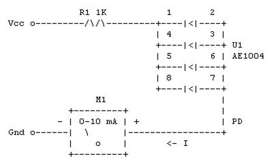
* The meter (M1) I used was a D'Arsenval moving coil type that had a full scale sensitivity of 10 mA. A suitable shunt can be used with a more sensitive meter or just use one of the current ranges of your VOM or DMM.
R1 provides current limiting to protect the meter movement from vaporization should the photodiode array short out. The combination of Vcc and R1 just needs to meet the requirement that the photodiode array remains reverse biased at the maximum expected current (optical power).
For the value of R1 shown above, Vcc should be at least 4 VDC for a photodiode current up to about 3 mA.
* I do not know the maximum ratings of this photodiode array but it seems to be fine with Vcc up to at least 12 VDC. Since current is nearly independent of the bias voltage, Vcc is not at all critical.
* Sensitivity is about .45 mA/mW at 632.8 nm from a HeNe laser. Though I have nothing precise to calibrate it against, the readings were consistent and linear with the tubes I tried which had their output power labeled.
* Mount the photodetector on a 'third hand' type of mount so it can be easily positioned in the beam path.
* A lens can be used to reduce the beam diameter of your laser so that the entire beam fits within the area of the photodetector. Where the beam profile exceeds the dimensions of the photodetector, an estimate of beam power can still be made knowing the ratio of sensor area to total beam area.
Unfortunately, with the small area of the photodetector, using this with intact CD laser optics may not be that easy.
* The range of wavelengths over which this is useful should extend throughout the visible spectrum into the near IR - at least until 850 nm or so.
I do not know what precise effect different wavelength lasers will have on the sensitivity of this circuit. Shorter wavelengths are more energetic but generate the same number of charge carriers (i.e., same current) and have less chance of surviving the trip through the diode junction. Thus, for a given photon flux the power reading will be low at shorter wavelengths. A correction factor can probably be computed.
* I also do not have any idea at what point the photodiode array will be damaged due to thermal effects. This is certainly not a problem for up to 10 mW as long as it is not focused to a sharp point.
A pair of op-amps can be added to provide more flexibility. The following circuit is substituted for the meter (M1), above. Any general purpose op-amps (e.g., 741) powered from +/- 12 VDC (for 10 V full scale) can be used. 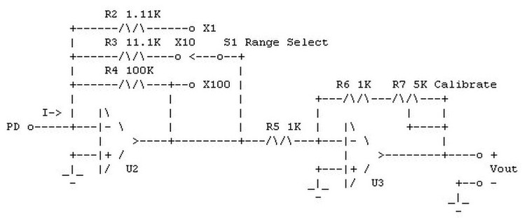
This circuit provides 3 ranges. R7 (calibrate) allows the sensitivity to be adjusted for your particular photodiode and laser wavelength. With R7 set to 1.22 K, the ranges will be .01 mW, .1 mW, and 1 mW per V of Vout at 632.8 nm. Vout can also be monitored with a scope or connected to an audio amplifier to detect an amplitude modulated laser beam.
For the Range Select switch (S1), make-before-break contacts are recommended to prevent high amplitude glitches when changing ranges.
For my photodiode array, the dark current was insignificant. Should this not be the case with your device a potentiometer tied to a negative reference can be used to null it out by injecting an equal and opposite current at the (-) input to U2.
Many variations and enhancements to this circuit are possible.
About laser speckle and other phenomena
Speckle is a mottled pattern that arises when laser light falls on a non-specular reflecting surface. Lasers with high spatial and temporal coherence properties are likely to produce dramatic speckle effects. Thus, gas lasers like HeNe types are more likely to exhibit this effect than laser diodes.
For those applications where the laser's bright light and its ability to be sharply focused or easily collimated are important but coherence is irrelevant, speckle is an undesirable side effect to be avoided.
(From: Mike Poulton (tjpoulton@aol.com)).
If you want any more information on any kind of laser, or sources for parts to build them, post your question on alt.lasers. There, a group of about ten laser enthusiasts (including myself) will jump on your question and answer it in every possible way and in great detail.
As for the speckle pattern, that is usually called the interference pattern. It has nothing to do with your eyes and has no bearing on how well you can see as it is a real phenomenon. Laser light is completely monochromatic and is also in phase. When this light is scattered, it gets out of phase and the waves collide. When a wave at a low point and a wave at a high point collide, they cancel each other out (just like those noise-reduction machines that send out ambient sound 180 degrees out of phase, except this is with light). Where the light cancels itself out, there is a dark space, where it does not, there is a light space. This creates a three-dimensional lattice-work of light and dark spaces.
As you move around it, you see different parts of the lattice and your view appears to move. The more "saturated" the area is with light, the more impressive this effect is. I have a 15mW Helium-Neon laser, and its effect is incredible. To say that this is in your head is like saying that it is an optical illusion when you look at different sides of a house. One cool thing to try is shining the laser into flood light (while it is turned off). The reflective coating on the inside of the bulb makes this effect very intense.
(From: J. B. Mitchell (ugez574@alpha.qmw.ac.uk)).
Speckle noise arises because of the highly coherent nature of the laser light and can thus be reduced or eliminated by reducing the coherence of the source. One easy way of achieving this is by introducing a rotating ground-glass screen into the beam. Placing the ground glass at the focus of the beam reduces the temporal coherence by introducing random phase variations while maintaining the spatial coherence (ability for the beam to be focused to a point). Putting the ground glass in an unfocussed beam reduces both the temporal and spatial coherence.
Alternatively, if you need to maintain the coherence for your application (interferometry, for example) the you can reduce the size of the speckles by increasing the aperture of the imaging system.
(From: Steve McGrew (stevem@comtch.iea.com)).
I know of three ways:
1. Increase the spatial frequency of the speckle so that it is so high it ceases to be a problem.
2. Use only specular objects and sources.
3. Decrease the temporal and/or spatial coherence of your laser beam by running it through something like a rotating diffuser.
Difference between Fabry-Perot and DFB lasers
The Fabry Perot laser design is what most people think of: lasing medium with mirrors at each end.
(From: Dr. Mark W. Lund (lundm@acousb)).
A Fabry-Perot cavity is the standard run of the mill cavity with two highly reflecting mirrors bouncing the light back and forth, forming a standing wave. This cavity is not very frequency selective, theoretically you could have 1 mm wavelength light and .001 micron wavelength light in the same cavity, as long as the mirrors are the right distance apart to form a standing wave (and higher order modes make this easier than you might think).
A distributed feedback laser replaces the back mirror with a grating along the cavity axis. Instead of being reflected abruptly like a metal mirror would, the grating reflects a little over each part of the grating until at the back of the grating the light has petered out. Of course, since the light is being reflected by the grating the reflected light is always in the correct phase no matter if it was reflected from the front or back of the grating. The distributed nature of the reflection sharpens the cavity resonance and distributed feedback lasers are typically of much narrower bandwidth than the same laser with mirrors. Mostly seen in laser diodes, distributed feedback can also be done with non-linear optics, volume gratings, and other more esoteric optical elements.
(From: Bret Cannon (bd_cannon@pnl.gov)).
Fabry-Perot lasers are made with a gain region and a pair of mirrors on the facets, but the only wavelength selectivity is from the wavelength dependence of the gain and the requirement for an integral number of wavelengths in a cavity round trip.
DFB (Distributed Feed Back) lasers have the a periodic, spatially-modulated gain, which gives a strong selectivity for the wavelength that matches the period of the gain modulation. DFB lasers lase in the same single longitudinal mode from threshold up to the maximum operating power while Fabry-Perot lasers hop from one longitudinal mode to another as the current and/or temperature change. Most Fabry-Perot lasers lase on several longitudinal modes simultaneously though with some of these lasers you can find currents and temperatures where they lase on only a single mode.
There are also DBR (Distributed Bragg Reflector) lasers that have a Bragg reflector, that is a volume grating, as the reflector at one end of the cavity, which provides wavelength selective feedback. These lasers lase on a single longitudinal mode but the lasing hops from longitudinal mode to longitudinal mode to stay near the peak of the reflectivity of the Bragg reflector as temperature and current are changed.
Comments on various color lasers
(From: Mike Poulton (tjpoulton@aol.com)).
Laser diodes have only been able to produce red and infrared beams so far (at least commercially). There have been some research reports of green and possibly blue laser diodes but only operating in pulse mode, at reduced temperature, and/or with very limited lifetime. This will no doubt change as enormous incentives exist to develop shorter wavelength laser diodes for numerous applications.
The green lasers you see are either argon or frequency-doubled Nd:YAG (neodymium doped yittrium-aluminum-garnet). The argon laser is a very large and complex device, almost always putting out hundreds of times the power of your pointer. A Nd:YAG laser is usually even more powerful, but is often pulsed. Diode lasers are not used in laser light shows because they are never powerful enough. I am sitting here typing this while allowing my 15mW Helium-Neon laser to stabilize and warm up. Its wavelength is shorter, and it is 3 times more powerful than the pointer. When a red beam is needed in a laser light show, these are usually used because they are usually more powerful than diodes, and the beam is more visible per milliwatt because of it's shorter wavelength. Happy Lasing, and be sure to visit alt.lasers for any laser info you need!
Comments on spatial and temporal coherence
(From: Daniel Marks (dmarks@uiuc.edu)).
There are really two coherences associated with any source; spatial and temporal coherence. Probably the coherence you are referring to is temporal coherence, but both are important for holography.
The temporal coherence is related to the bandwidth of the source. The more narrow the bandwidth of the source, the longer the coherence length. HeNe lasers have a very narrow bandwidth, as a result they have a coherence length on the order of 10-30 cm. LED's are incoherent sources, they only have a coherence length of 10-40 microns, and a large bandwidth of several kT (25.9 meV at 298K) or I'm guessing 10 nm of bandwidth (around about 650 nm). HeNe lasers are also much more spatially coherent than LEDs. The spatial coherence length is determined by the cavity and cavity reflectivity in a laser. LEDs also have a very short spatial coherence length, or only a couple of wavelengths.
The coherence length is the maximum distance at which two points in the field can be interfered with contrast. The temporal coherence length determines the maximum depth of the object in a reflection hologram, and the spatial coherence length determines the lateral size. Using techniques of "white light" interferometry, incoherence sources can be used, but they are tricky and have many restrictions on the kinds of holograms one can create.
Laser beam collimation
(From: Kai-Martin Knaak (kmk@physik.uni-mainz.de)).
There is a maximum distance that a beam of light can be kept collimated. Usually it is called 'Rayleigh length' and it depends on the wavelength and the minimum diameter of the beam. If the beam diameter is w0 at point z, then the beam will have expanded to at least 1.4 times w0 at Rayleigh-length distance from z.
The Rayleigh length, z_rayleigh, can be calculated like this:
_rayleigh = pi * (minimum diameter)/(wavelength)
For example, assuming a HeNe laser (632.8 nm) and a minimum diameter of 6 mm this makes about 180 meters. In practice, you might not get that far but 50 meters may be feasible. (Reality enters due to the fact, that the axial intensity distribution is assumed to be perfectly gaussian.)
One way of doing the collimation, is with a telescope consisting of two identical plano-convex lenses. If the lenses are spaced at the double focal length, their effect onto beam divergence will vanish. Putting them nearer increases divergence and moving them farther apart focuses the beam. So you can collimate the beam by fine tuning the lens distance.
Of course lens aberrations limit the performance, so weak lenses or aspheric lenses might be desirable. Spherical aberration will be reduced by turning the curved sides of the lenses face to face.
See the book "Lasers" by A. E. Siegmann for the details of the propagation of laser light. (page 664 ff.)
General comments on lasers as a hobby
We have addressed the issues involved in using common laser diodes and HeNe laser tubes. If you are really serious and want to go further, here are some comments on a variety of lasers.
(From: Richard Alexander (RAlexan290@gnn.com)).
How much do you like to build things? Would you prefer to assemble a bunch of parts, or do you want to blow your own glass tubes, too? Do you have any mechanical experience? Do you build electronic kits? Keep in mind that you will often be working with intense light (enough to instantly damage your unprotected eyes, and maybe your unprotected skin) and high voltages.
All laser experimenters (and optics types, too) should have a copy of "Scientific American"'s "Light and Its Uses." It gives construction plans for a Helium Neon (you blow the glass tube yourself), an Argon Ion (even more complicated), a CO2 (designed and built by a high school student, and able to cut through metal), a dye, a nitrogen (a great first laser, but watch out for UV light) and a diode laser (obviously, you buy the diode laser and assemble the driver circuit from the plans they supply). They also explain how to make holograms using visible and infrared light, microwaves and sound. There are other projects, too. The book is getting fairly old (the HeNe dates to the '60s or '70s), but it's still a great reference.
A nitrogen laser may be built for under $200 (maybe less than half that amount if you are lucky). It requires no mirror alignment (since it has no mirrors). The technology for building this laser was available to Ben Franklin, so there is nothing too critical in it. The hazards it presents are lots of ultraviolet light (spark discharges and laser beam), high voltage (necessary to arc across a 1/4 inch spark gap in a nitrogen environment) and circuit etcher (the main capacitor is made from an etch circuit board).
Once built, the nitrogen laser can drive many other projects. It can be used as a pump for the dye laser, for example. It will light up anything fluorescent. It is a pulse laser (10 ns) that can be repetitively pulsed (120 Hz is a likely frequency). Megawatt power is possible, but the total energy is low (due to the short pulses).
"Electronics Now" (formerly, Radio Electronics) has a laser projects column that started several months ago. I'm trying to think up a project I can submit to them. They said they would welcome projects for the laser column.
Helium Neon laser tubes may be bought from many mail-order companies. I bought one from Meredith Instruments in Arizona. They cost about $15, and the power supply can be built or bought for about another $20. You have the option of buying tubes with mirrors attached or not. You might want to buy the mirrors attached, because aligning those mirrors is extremely tedious. I was given an "A" for constructing a working Helium Neon laser from the parts in the Laser Lab in less than an hour. The class was given two semesters to gain the experience they needed to do that.
If you want more than one color from lasers, there are various ways to do it, but none of them are as nice as one might like. For $3000 or so, you can buy a Helium Neon laser that will produce laser light ranging from infrared to blue. All you have to do is turn a dial on the back.
Laser light shows usually use Argon Ion or Krypton lasers. These are able to produce most of the colors of visible light, and they can also be dialed to the desired color. However, they usually cost several thousand dollars ($40,000 is not too unusual) and require either forced air or water cooling or a combination.
Laser Information Resources
References on laser principles
1. The Laser Cookbook: 88 Practical Projects
Gordon McComb
TAB Books Inc, 1988.
Blue Ridge Summit, PA 17214
2. Build your own Laser, Phaser, Ion Ray Gun & Other Working Space Age Projects
Robert E. Iannini
TAB Books, a division of McGraw Hill,
1983 Blue Ridge Summit, PA 17214
ISBN 0-8306-0604-1 paperback
3. Build your own working Fiberoptic, Infrared, and Laser Space-Age Projects
Robert E. Iannini
TAB books, a division of McGraw-Hill, 1987
Blue Ridge Summit, PA 17214
ISBN 0-8306-2724-3
This includes plans for a HeNe power supply as well as complete ruby/Nd-YAG and CO2 lasers and other interesting stuff.
4. Try the magazine Scientific American, the column Amateur Scientist, the time period 1960-1980.
5. Light and its Uses
(readings from Scientific American) C. L. Strong's 'The Amateur Scientist' with introductions by Jeral Walker.
W. H. Freeman And Co.
ISBN 0-7167-1184-2, ISBN 0-7167-1185-0 (pbk).
Info on how to build lasers and how to use them, as well as info on building laser instruments.
All of John Strong's (genius experimentalist) and Jeral Walkers columns on photonic devices are in this absolutely fabulous book.
The book describes the manufacture of several lasers by amateurs, form HeNe through CO2 and Dye types. Also, some Hologram and interferometer stuff. It is not for the absolute beginner but suitable for anyone who has some considerable hobbyist type experience with electronics and/or lasers.
6. Some older issues of Popular Electronics and Radio Electronics have articles on how to use HeNe lasers and power supplies for them (maybe 1980-1989).
7. Forrest Mims' Circuit Scrapbook II
Forrest Mims
Howard Sams & Co., 1987
This book is out of print but available at some libraries. It provides various driver circuits and a miniature laser + driver + battery built into a very small package.
Forrest Mims has also written a number of articles on how to use and build lasers.
8. The Laser Book - A New Technology of Light
Clifford L. Lawrence
Prentice Hall Press, 1986
A division of Simon and Schuster
New York, NY 10023
ISBN 0-13-523622-3
This book includes descriptions of many common lasers, construction, and applications.
9. Lasers and their Applications.
Kurt R. Stehling
The World Publishing Company, 1966
Cleveland and New York
Library of Congress Catalog Number: 66-18464
10. Introduction to Laser Physics
Bela A. Lengyel
John Wyley and Sons, Inc., 1966
New York, London, Sydney
Library of Congress Catalog Number: 65-27659
If you always wanted to really understand terms like population inversion, hyperfine transitions, and quantum efficiency, this old but solid book is for you. Be prepared for some heavy math. However, it does include some practical aspects of laser construction as well.
11. Wedding Lasers to Power Supplies
Photonics Spectra, June 1982
This is a nice article on general power supply considerations for HeNe and (small) CO2 lasers.
12. Another place you may try is "The Bell Jar" a newsletter on high vacuum amateur work it sometimes includes laser information. They have a WEB site: http://www.tiac.net/users/shansen/belljar/articles.htm.
13. Some of the earlier columns of "The laser Experimenter" (1995) went into detail on how to make light shows, and how to construct the power supplies for the HeNe type of lasers.
14. The March 1989 issue of Radio-Electronics magazine has plans for a HeNe power supply running on 12 VDC using a 555 timer chip and two transistors, a relay, and a 12 V to 280 V step-up transformer.
You may be able to find many of these items in a large public library. I think that the old issues of magazines are often on microfilm or microfiche.
Web resources
The following site will be jointly hosted by Ed Edmondson Jr. and myself:
http://www.geocities.com/CapeCanaveral/Lab/3931/
"Our mission here is to provide informtion about Lasers and Laser related equipment to the Amateur, Hobbyist, and Experimenter. Our site is the focal and collecting point of FREE information about these wonderful light emitting devices and their technology."
A current version of this document will always be present in some form at this site. The following have various information and links to other laser related sites:
* http://www.misty.com/~don/laserdon.html (Don Klipstein's lighting center)
* http://www.rli.com/ (Lasernet homepage)
* http://www.rli.com/tutor1.html (Lasernet Laser tutorial)
* http://www.achilles.net/~jtalbot/history/ (History of lasers)
* http://www.rli.com/lazindex.html (Links to laser related sites)
Copyright (C) 1994,1995,1996,1997 - Samuel M. Goldwasser