

12.0 Description & Modeling of Cascade Thermoelectric Modules
12.1 A standard single-stage thermoelectric cooling module is capable of achieving a maximum no-load temperature differential (DTmax) of approximately 72°C. It is possible to obtain DTs of up to 130°C by mechanically stacking modules on top of one another whereby the cold side of one module becomes the hot side of another module mounted above. This stacking arrangement is called a Cascade or Multi-Stage module configuration. Cascade modules usually, but not always, have a pyramid shape thereby the higher stages are physically smaller than those below. Regardless of the physical shape, however, lower stages must always have greater heat pumping capacity than the higher stages. although cascade configurations of up to six and seven stages have been constructed, practical cascade devices usually have from two to four stages.
The principal factor that limits cascade module performance is related to the temperature dependent properties of the thermoelectric semiconductor materials. The performance of Bismuth Telluride alloys used in most thermoelectric coolers generally peaks near 70°C and performance falls-off appreciably at lower temperatures. Consequently, cascade modules exhibit a condition of diminishing returns where, as successive stages are added, the increase in DT becomes smaller.
Figure (12-1)
Performance Graph of a Typical Cascade Module
12.2 MODELING OF CASCADE MODULES: Modeling of cascaded or multi-stage thermoelectric coolers is somewhat more complicated than for single-stage devices. With multi-stage coolers, the temperature between each stage is critically important and module performance cannot be established until each interstage temperature value is known. With a two-stage cooler only one interstage temperature must be determined but, as more stages are added, the thermal analysis becomes increasingly complex. Manually calculating multi-stage module performance is extremely laborious, yet with a computer, the required calculations can be performed with little effort.
The most common method for computer-modeling cascade modules involves carrying out an iterative series of performance calculations beginning with assumed interstage temperature values. Using this technique, the performance of each stage is repeatedly calculated until the difference between successive interstage temperature calculations becomes very small (typically 0.1°C or less). When this point is reached, each of the relevant module performance parameters can be ascertained. Note that the temperature-dependent value of SM, RM, and KM must be converted as explained in paragraph 11.2.4 to reflect the number of couples in each stage together with their optimum TE element currents. The following paragraphs describe the calculations needed to model two and three-stage cascaded thermoelectric modules. Four and greater-stage modules may be modeled in a similar manner by expanding the three-stage calculation routines to include terms for each additional stage. Calculations of the various parameters should be performed in the order shown.
12.2.1 TWO-STAGE MODULE CALCULATIONS: A typical two-stage thermoelectric module is illustrated in Figure (12-2). The following new terms will be used in the module performance calculations:
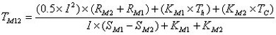
TM12 is the interstage temperature between stages 1 and 2 in °K
SM1 is the Seebeck coefficient of the 1st stage in volts/°K
SM2 is the Seebeck coefficient of the 2nd stage in volts/°K
RM1 is the resistance of the 1st stage in ohms
RM2 is the resistance of the 2nd stage in ohms
KM1 is the thermal conductance of the 1st stage in watts/°K
KM2 is the thermal conductance of the 2nd stage in watts/°K
Figure (12-2) a) The interstage temperature (TM12) in °K is:
b) Heat pumped (Qc) by the module in watts is:
![]()
c) The input voltage (Vin) to the module in volts is:
![]()
d) The electrical input power (Pin) to the module in watts is:
Pin = Vin x I
e) The heat rejected by the module (Qh) in watts is:
![]()
or
Qh = Qc - Pin
f) The coefficient of performance (COP) as a refrigerator is:
COP = Qc / Pin
12.2.2 THREE-STAGE MODULE CALCULATIONS: A typical three-stage module is illustrated in Figure (12-3). The following new terms will be used in the module performance calculations:
TM23 is the interstage temperature between stages 2 and 3 in °K
SM3 is the Seebeck coefficient of the 3rd stage in volts/°K
RM3 is the resistance of the 3rd stage in ohms
KM3 is the thermal conductance of the 3rd stage in watts/°K
Figure (12-3) a) The lower interstage temperature (TM12) in oK is:
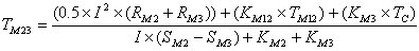
b) The upper interstage temperature (TM23) in °K is:
c) Heat pumped by the module (Qc) in watts is:
![]()
d) The input voltage (Vin) to the module in volts is:
![]()
e) The input power (Pin) to the module in watts is:
Pin = Vin x I
f) The heat rejected by the module (Qh) in watts is:
Qh = Qc + Pin
g) The coefficient of performance (COP) as a refrigerator is:
COP = Qc / Pin