

5.0 Heat Sink Considerations
5.1 Rather than being a heat absorber that consumes heat by magic, a thermoelectric cooler is a heat pump which moves heat from one location to another. When electric power is applied to a TE module, one face becomes cold while the other is heated. In accordance with the laws of thermodynamics, heat from the (warmer) area being cooled will pass from the cold face to the hot face. To complete the thermal system, the hot face of the TE cooler must be attached to a suitable heat sink that is capable of dissipating both the heat pumped by the module and Joule heat created as a result of supplying electrical power to the module.
A heat sink is an integral part of a thermoelectric cooling system and its importance to total system performance must be emphasized. Since all operational characteristics of TE devices are related to heat sink temperature, heat sink selection and design should be considered carefully.
A perfect heat sink would be capable of absorbing an unlimited quantity of heat without exhibiting any increase in temperature. Since this is not possible in practice, the designer must select a heat sink that will have an acceptable temperature rise while handling the total heat flow from the TE device(s). The definition of an acceptable increase in heat sink temperature necessarily is dependent upon the specific application, but because a TE module's heat pumping capability decreases with increasing temperature differential, it is highly desirable to minimize this value. A heat sink temperature rise of 5 to 15°C above ambient (or cooling fluid) is typical for many thermoelectric applications.
Several types of heat sinks are available including natural convection, forced convection, and liquid-cooled. Natural convection heat sinks may prove satisfactory for very low power applications especially when using small TE devices operating at 2 amperes or less. For the majority of applications, however, natural convection heat sinks will be unable to remove the required amount of heat from the system, and forced convection or liquid-cooled heat sinks will be needed.
Heat sink performance usually is specified in terms of thermal resistance (Q):
![]()
where:
Qs = Thermal Resistance in Degrees C per Watt
Ts = Heat Sink Temperature in Degrees C
Ta =Ambient or Coolant Temperature in Degrees C
Q = Heat Input to Heat Sink in Watts
5.2 Each thermoelectric cooling application will have a unique heat sink requirement and frequently there will be various mechanical constraints that may complicate the overall design. Because each case is different, it is virtually impossible to suggest one heat sink configuration suitable for most situations. We have several off the shelf heat sinks and liquid heat exchangers appropriate for many applications but encourage you to contact our engineering department.
Note that when combining thermoelectric cooling modules and heat sinks into a total thermal system, it normally is NOT necessary to take into account heat
loss or temperature rise at the module to heat sink junctions. Module performance data presented herein already includes such losses based on the use of thermal grease at both hot and cold interfaces. When using commercially available heat sinks for thermoelectric cooler applications, it is important to be aware that some off-the-shelf units do not have adequate surface flatness. A flatness of 1mm/m (0.001 in/in) or better is recommended for satisfactory thermal performance and it may be necessary to perform an additional lapping, flycutting, or grinding operation to meet this flatness specification.
5.2.1 NATURAL CONVECTION HEAT SINKS: Natural convection heat sinks normally are useful only for low power applications where very little heat is involved. Although it is difficult to generalize, most natural convection heat sinks have a thermal resistance (Qs) greater than 0.5°C/watt and often exceeding 10°C/watt. A natural convection heat sink should be positioned so that (a) the long dimension of the fins is in the direction of normal air flow, vertical operation improves natural convection and (b) there are no significant physical obstructions to impede air flow. It also is important to consider that other heat generating components located near the heat sink may increase the ambient air temperature, thereby affecting overall performance.
5.2.2 FORCED CONVECTION HEAT SINKS: Probably the most common heat-sinking
method used with thermoelectric coolers is forced convection. When compared to natural convection heat sinks, substantially better performance can be realized. The thermal resistance of quality forced convection systems typically falls within a range of 0.02 to 0.5°C/watt. Many standard heat sink extrusions are available that, when coupled with a suitable fan, may be used to form the basis of a complete cooling assembly. Cooling air may be supplied from a fan or blower and may either be passed totally through the length of the heat sink or may be directed at the center of the fins and pass out both open ends. This second air flow pattern, illustrated in Figure (5.l), generally provides the best performance since the air blown into the face of the heat sink creates greater turbulence resulting in improved heat transfer. For optimum performance, the housing of an axial fan should be mounted a distance of 8-20mm (0.31-0.75") from the fins. Other configurations may be considered depending on the application.
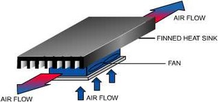
Figure (5.1) Forced Convection Heat Sink System Showing Preferred Air Flow
The thermal resistance of heat sink extrusions often is specified at an air flow rate stated in terms of velocity whereas the output of most fans is given in terms of volume. The conversion from volume to velocity is:
Velocity = Volume / Cross-sectional Area of Air Passage
or: Linear Feet per Minute = Cubic Feet per Minute / Area in Square Feet
or: Linear Meters per Minute = Cubic Meters per Minute / Area in Square Meters
5.2.3 LIQUID COOLED HEAT SINKS: Liquid cooled heat sinks provide the highest thermal performance per unit volume and, when optimally designed, can exhibit a very low thermal resistance. Although there are many exceptions, the thermal resistance of liquid cooled heat sinks typically falls between 0.01 and 0.1°C/watt. Simple liquid heat sinks can be constructed by soldering copper tubing onto a flat copper plate or by drilling holes in a metal block through which water may pass. With greater complexity (and greater thermal performance), an elaborate serpentine water channel may be milled in a copper or aluminum block that later is sealed-off with a cover plate. We offer several liquid-type heat sinks that may be used advantageously in thermoelectric systems. With other commercial heat sinks, always check the surface flatness prior to installation. While liquid cooling may be considered undesirable and/or unsatisfactory for many applications, it may be the only viable approach in specific situations.